We looked at various forms of on-PCB serial communication with the MCS-51 / 8051 microcontroller family in previous posts: UART, Dallas 1-Wire, and Philips I2C. Now, let’s look at the pinnacle
of short-range wireless interfacing from the 1970s and 1980s: the Infrared Data Association (IrDA).
Growing up in East Germany in the 1980s, infrared remote controls were the exception. You had to walk up to the TV set
to change the channel or volume. Due to communist five-year planning and exorbitant TV set prices, most families only had one TV set
in the household, which was usually quite dated. We had a Choromat 2160 from 1978 that lasted well into the 1990s. It had mechanical push-buttons on the front panel for channel selection and volume control.
There was one mechanical tuner to set the desired channel frequency for eight radio buttons (i.e., your saved channels).
However, my aunt, a college student at the time, was an aspiring electronics engineer. As an electronics person, she had the chance
to end up in one of two prestigious East German companies: RFT (Rundfunk- und Fernmelde-Technik) or Robotron (the company that
reverse engineered the Z80 from Toshiba wafers). With proper East German
hands-on education, she ended up doing work
terms at RFT in the 80s. Suddenly, my great-grandma, my grandma, and other family members had a TV set with a remote control.
I was a kid, but I gather they were not subject to an employee discount under socialism. The pinnacle back then was
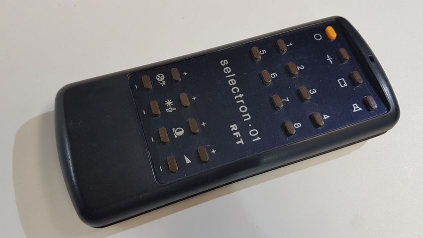
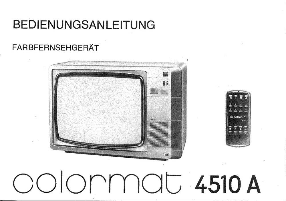
the RFT Colormat 4516 with the Selectron-01 remote
control shown above.
Outside East Germany, infrared remote controls were becoming more common in the West in the late 70s and early 80s.
It was a huge improvement over previous remote control technologies that used ultrasonic sound waves or radio frequency (RF) signals.
Anyone who had dogs at home got the right feedback whenever changing channels with these.
IrDA Basics
Before 1994, there was no standardized way for devices to communicate using infrared light. Every vendor pretty much
rolled out their own protocol. The Infrared Data Association (IrDA) was formed in 1993 by a group of companies to create
a standard for infrared communication. The first IrDA standard was released in 1994, defining the physical layer, data link layer,
and application layer protocols for infrared communication.
From a hardware perspective, you need an infrared LED to transmit data and a photodiode or phototransistor to receive data.
To avoid adjacent channel interference, most receivers also have an optical filter that only allows infrared light at a specific wavelength
to pass through. The most common wavelength for IrDA communication is 850 nm. This is close enough to the quantum efficiency
of most CMOS and CCD sensors, so if you ever need to debug a transmitter, point it at a digital camera or smartphone camera.
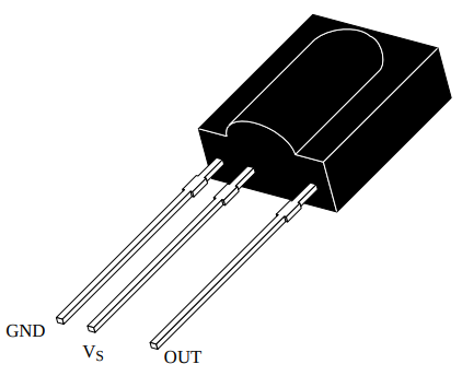
You can build a simple pulse former for the receiver out of a transistor circuit, or simply buy a photo module. A
common receiver is the TSOP17-Series by Vishay. It has a built-in bandpass filter and demodulator
circuitry. It can decode modulated IR signals at 36 kHz, 38 kHz, 40 kHz, or 56 kHz carrier frequencies. The module outputs
a digital signal that can be read directly by a microcontroller. Again, if you look at photodetectors in LCSC,
you will find a plethora of options. The issue is you need a matching bandpass filter for the carrier frequency you pick.
One issue to be aware of is modulation. To be immune to ambient light interference, IrDA communication uses
a modulated signal. Given the possibility of interference from other light sources, the IrDA standard uses a modulation frequency of 38 kHz,
which is high enough to avoid most ambient light interference but low enough to be easily generated and detected by simple electronics.
Once you have pulse forming set up, the next question is how to reliably code the signal so we can recover it on the other side.
Vishay has a good application note on IR Protocols that covers various protocols.
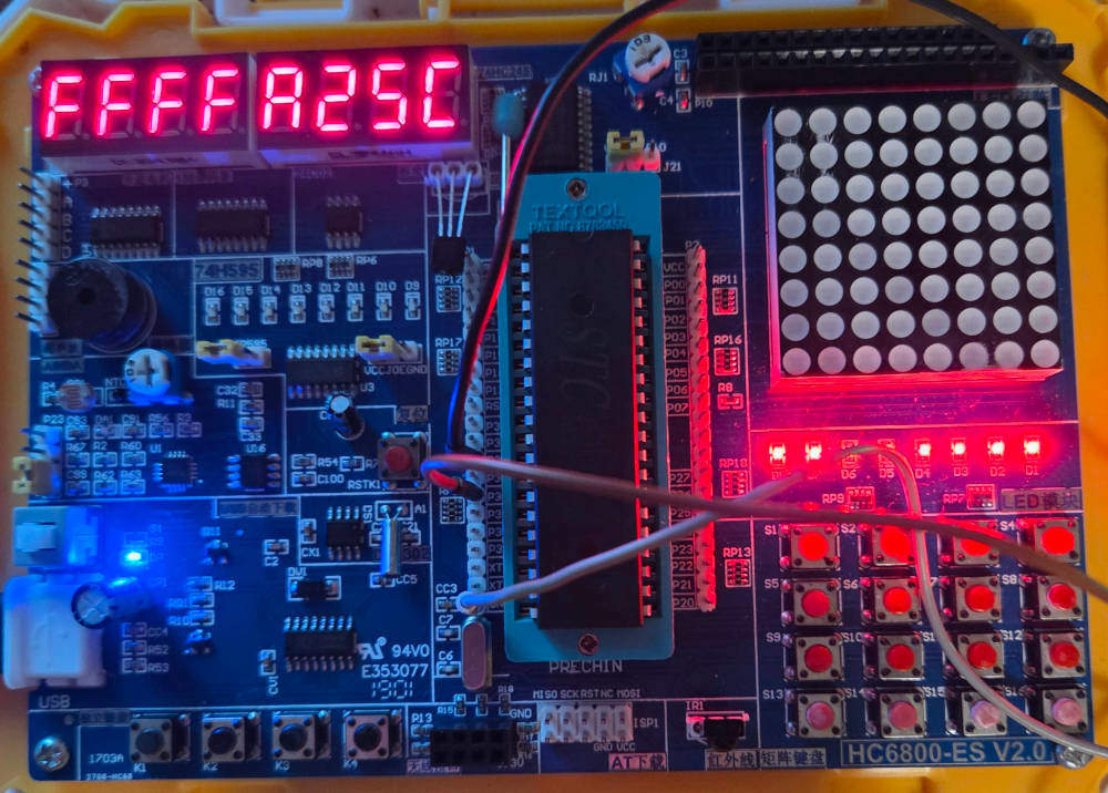
Looking at the HC6800-ES2 kit that we have been using for MCS-51 experiments, it has what looks like a TSOP17 module and
also came with a simple infrared remote control. However, the documentation does not say much about what modulation frequency
is chosen, or if this is actually a genuine Vishay part or a clone. So we trust the makers that they figured out the
right modulation frequency.
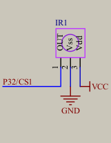
So the only thing we can use on P3.2 to assist with this is the external interrupt INT0. Now the question remains:
what protocol?
NEC Protocol
If we were to take it easy, we would just scrap the MCS-51 in favour of something that does C++ and port the IRremote library to that. However, that would not be in the
spirit of this blog series. So we reverse-engineer the remote control protocol by capturing the signals with a logic
analyzer. For that, I wrote a simple infinite program that just pulls P3.2 high and has a logic analyzer capture
the signal whenever a button is pressed on the remote control. The trace looks as follows.
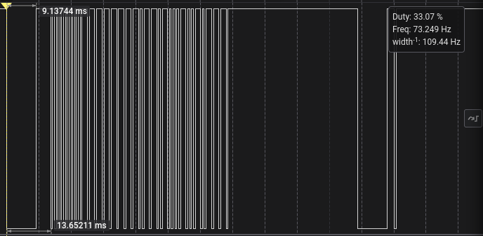
Honing in, the big telltale sign seems to be the valley at the beginning that is about 9 ms long, followed by what looks
like a sync pulse of about 4.5 ms. This is followed by a series of patterns that are either about 2250 µs long or about
1125 µs long. Then there is some form of repeat code every 100 ms. A quick web search pulled this up. It looks like we have the classic NEC protocol here, however,
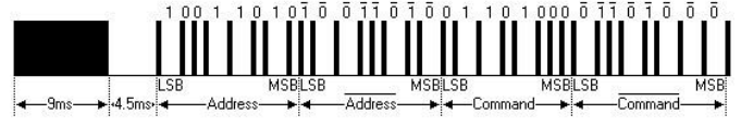
inverted by polarity. The NEC protocol uses pulse distance encoding to represent bits. Each bit consists of a fixed-length
pulse followed by a variable-length space. A logical ‘0’ is represented by a 562.5 microsecond pulse followed by a 562.5
microsecond space, while a logical ‘1’ is represented by a 562.5 microsecond pulse followed by a 1,687.5 microsecond space.
The NEC protocol starts with a 9 ms leading pulse burst (the valley we see) followed by a 4.5 ms space (the sync pulse).
The successor of NEC, Renesas, wants to sell you a programmable logic device to decode this,
but we are dealing with a microcontroller design here that dates back to the times when Kiana Tom was just beginning to experiment with Body Shaping courses on TV. We have an archaic 8-bit microcontroller with an
external interrupt pin and various internal timers. So let’s roll our own decoder.
One approach proposed here is to use a
resettable timer to measure the pulse widths. Since we are dealing with an inverted signal, we set up the external interrupt
to trigger on the falling edge and have a free-running timer in the background that measures ms intervals.
- Whenever the timer overflows, we increment a global millisecond counter up to a maximum.
- If the falling edge occurs, we copy the
ms counter and reset it to zero. - If
ms exceeds the maximum interval for a pattern, we consider this the start of a frame and start counting pulses, ignoring the first two edges of the sync pattern. - If a pulse exceeds
2 ms, we consider this a logical ‘1’; otherwise, a logical ‘0’. - After receiving 32 bits, we lock it in.
We have slightly different timing due to the external 12 MHz. We also embrace open-source SDCC as our toolchain of choice,
not Keil. So here is the code to set up the timer and external interrupt.
We can use The timer Tool to come up with
a 1 ms timer configuration.
12 MHz, 12 T mode- Timer 0 in
16-bit mode 1 ms target interval
void timer0_init(void) {
TMOD &= 0xF0;
TMOD |= 0x1;
TH0 = 0xfc;
TL0 = 0x18;
TF0 = 0;
TR0 = 1;
ET0 = 1;
}
Use the Interrupt Tool to set up the external interrupt on P3.2 for falling edge triggering.
- Enable
INT0 P3.2 falling edge.
void ext_init(void) {
IT0 = 1;
EX0 = 1;
}
For the timer interrupt service routine (ISR), we just toggle a heartbeat LED on P3.4 and increment the ms counter
up to a maximum of 50 ms. The P3.4 toggle was mapped to the logic analyzer to help with debugging. I had issues
where stcgal would sometimes put the MCU in 6T mode instead of 12T mode, messing up the timing. The heartbeat
helped verify that the timer interrupt was firing at the expected rate.
uint8_t ms_counter = 0;
int8_t pulse_count = 0;
uint32_t pattern = 0;
uint32_t last_pattern = 0xFFFFFFFF;
void tf0_isr(void) __interrupt(TF0_VECTOR) {
P3_4 = !P3_4;
TH0 = 0xfc;
TL0 = 0x18;
if(ms_counter<50) {
ms_counter++;
}
}
The external interrupt ISR is more involved. We copy the current ms counter, reset it for the next pulse, and then
process the pulse based on the current state. If the ms counter was 50, we consider this a timeout and assume
a sync pulse. We reset the pulse counter and pattern. If we are within the first 31 pulses after sync,
we record the bits based on the pulse width. After 32 bits, we lock in the pattern.
void int0_isr(void) __interrupt(IE0_VECTOR) {
uint8_t cur_timer = ms_counter;
ms_counter = 0;
TH0 = 0xfc;
TL0 = 0x18;
pulse_count++;
if(cur_timer == 50) {
pulse_count = -2;
pattern = 0;
} else if(pulse_count >= 0 && pulse_count < 31) {
if(cur_timer>= 2) {
pattern |= 0x00000001 << (31 - pulse_count);
}
}
if(pulse_count >= 32) {
last_pattern = pattern;
}
}
Then we recycle the main from the 7-Segment Display post to display the received pattern
on the 8-digit 7-segment display. For initialization, we set the pattern to 0xFFFFFFFF to indicate no valid
pattern has been received yet.
void main(void) {
timer0_init();
ext_init();
EA = 1;
P0 = 0x00;
P2 = 0x00;
for(;;) {
for(uint8_t i=0; i<8; i++) {
P2 = i<<2;
uint8_t nibble = (last_pattern >> i*4) & 0x0F;
LED_DIGIT = segment_map[nibble];
delay(200);
LED_DIGIT = 0x00;
}
}
}
Summary
As for the East German TVs, these lasted well into the 2000s. Unfortunately, RFT did not. In a sad turn of events,
after several rounds of restructuring,
they were eventually acquired by TechniSat as a hollow shell of what they once were in 1998.
One of the first things that died, even before the 90s, were partnerships with East German universities and hands-on
training programs. In the end, my aunt did not become an electronics engineer when the program was scrapped. So not
everyone got the uplift from the fall of the Iron Curtain. While everyone else east of it got to enjoy recycled 70s
and 80s Western TV series and dubbed Kiana Tom and Cindy Crawford fitness videos on TV …
… with remote in hand. Full source code here
Published: 2025-11-24
Updated : 2025-11-24