It cannot be too early to get kids into STEM and related fields. After two years of COVID-forced zoom classes, the last
thing that comes to mind is to engage kids more in computer-based learning. Instead, it makes much more sense to learn
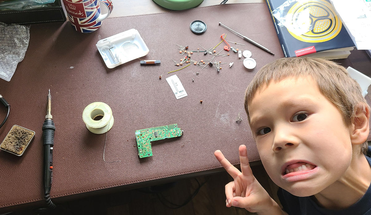
hands-on skills. This is a short report on how my son and I assembled a radio kit that we bought online to get him into soldering skills. This looked like a cool father-son project to attempt with just
basic soldering tools, some fine screwdrivers and a multimeter.
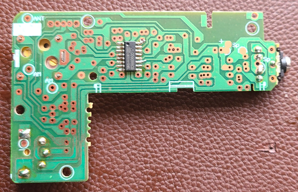
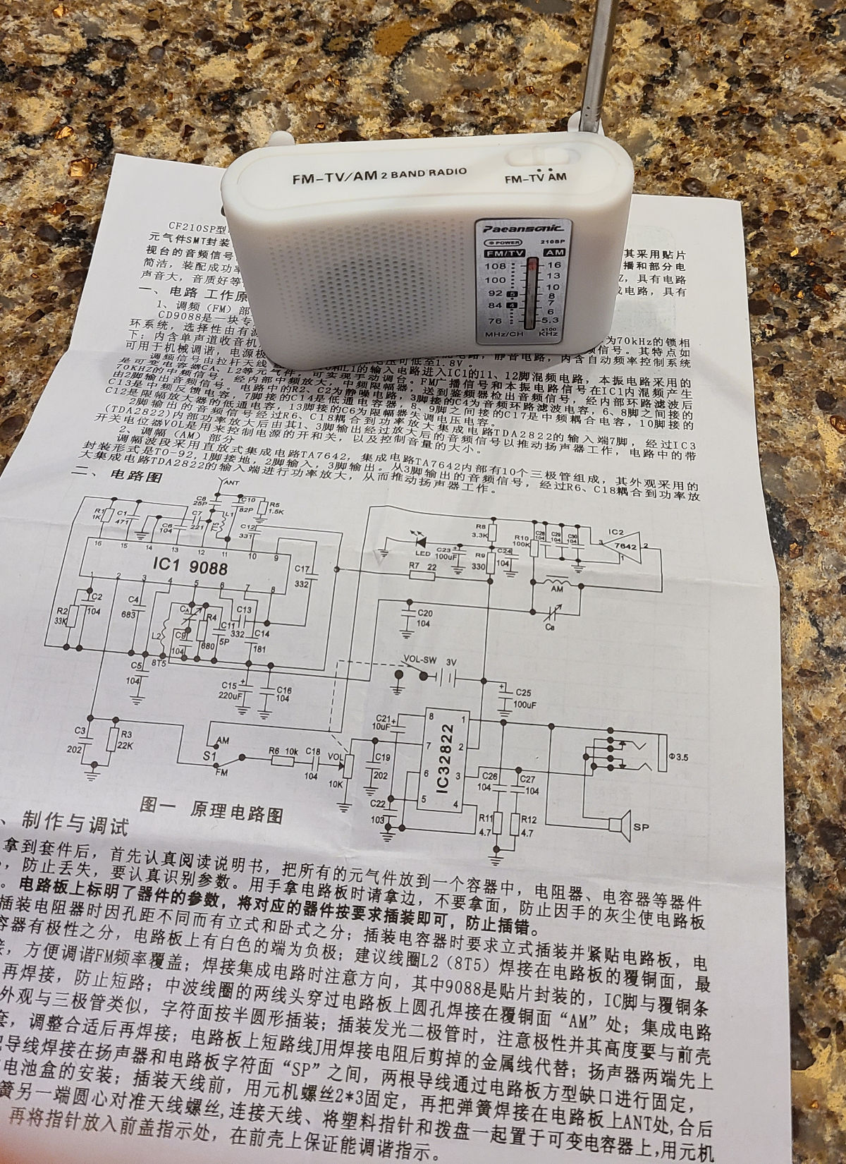
The kit comes with instructions in Simplified Chinese. From the model
numbers, it appears the main Tuner IC is a clone of a popular Phillips (now NXP) tuner IC that is still heavily used in
low-end radios in Mainland China, the second IC is a clone of a popular amplifier. Ironically, instead of the clone from
the documentation, the original (or at least
originally marked) amplifier IC was included. All other components are simple through-hole assembly parts. In addition
to the instructions, there is a small paper slip that has a detailed printout of the top silkscreen of the printed
circuit board, as the crude manufacturing process for the single-sided PCB washed out some component placement
markings.
The first task was to take inventory of all the parts. All parts were included but there was no provision for any spares.
If you misplace a resistor or capacitor you are out of luck. Also, the pre-cut wires to connect the PCB to the battery
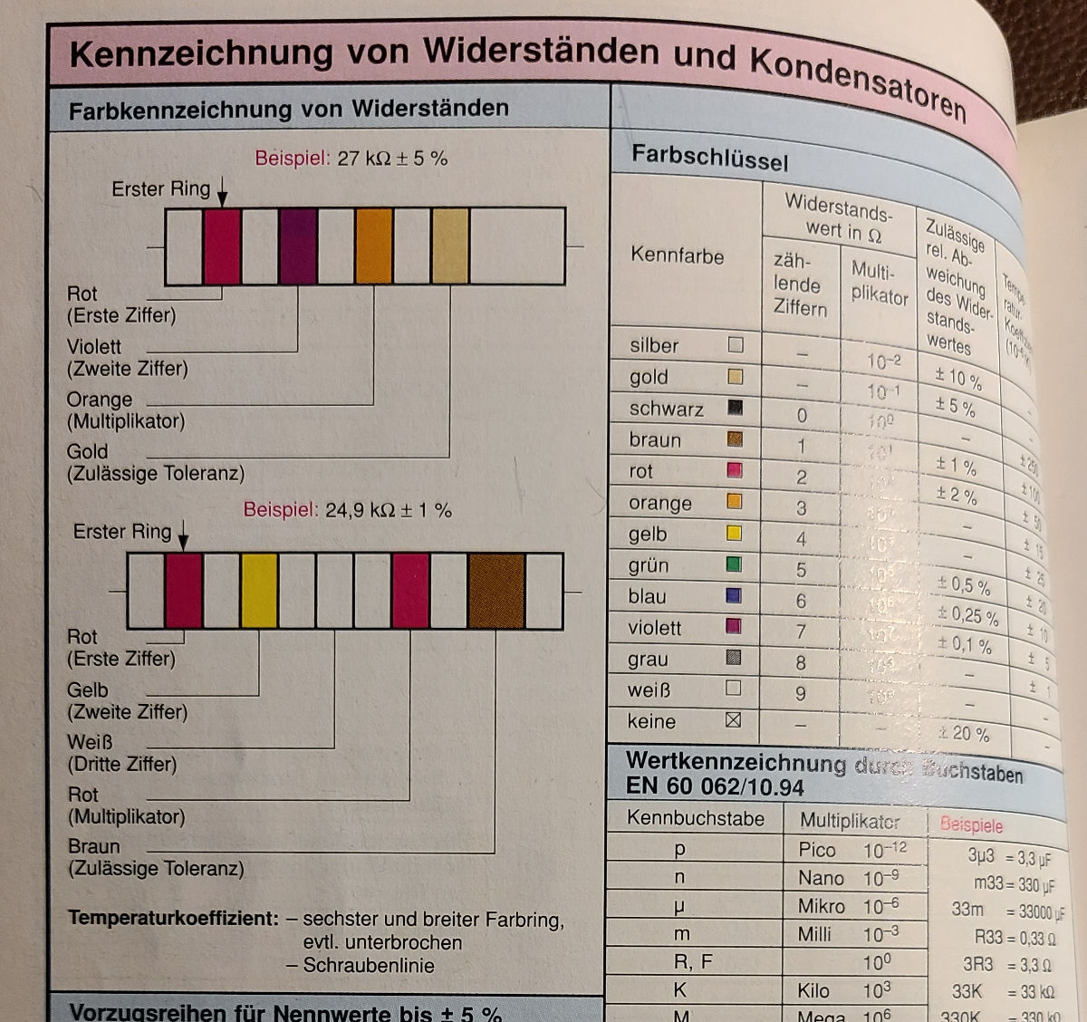
terminals and the FM antenna are rather short, we replaced these with longer ones. I had my son sort all components by
ratings. The resistors were sorted by color, so we could match up the colors with the rating. The Chinese instructions
seem to have an explanation of how this is done, but with limited Mandarin skills, we opted to use my old book of tables
instead. The capacitors have ISO markings too but you can match up the ISO marking with the PCB silkscreen.
While any kid can easily learn how to assemble through-hole components, soldering surface-mount devices (SMD) such as
the main tuner IC is more tricky and needs a lot of practice. So I put that on for him.
After all components, except for the AM antenna, were assembled. We decided to do a smoke test: Will it run? It in fact
did and the familiar white noise was coming out of the speaker.
Since the (low-cost) components in the kit have fairly wide tolerances the radio has to be calibrated to the displayed
range. Depending on your availability of FM stations, dial it either in at the top or bottom range. We picked Dave FM at
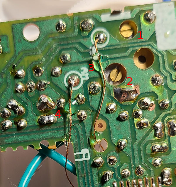
about 107.5MHz. This was fairly close to the prescribed 108MHz top range. Then turn screw (2) until you have that radio
station in tune. To give it 500kHz more range, we overturned it a bit and then dialed the tuning knob down a notch. The
frequency gauge of the plastic enclosure is a simple snail spring that gets screwed to the tuning knob. After installing
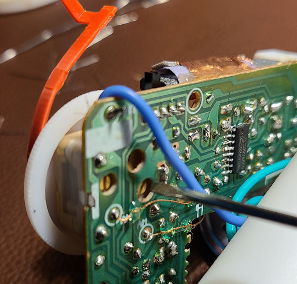
the AM antenna the procedure has to be repeated with knob (2) on the AM band. The loose coper wires that had to be
soldered for the AM antenna looked like a risky bet to leave loose, we dabbed them in hot glue (3, 4) to avoid shorting
out any other circuits.
Antenna tuning.
The final box build looks respectable. We both feel like we might pass the employment test for a Chinese radio factory.
References
Published: 2022-05-24
Updated : 2025-10-04
Not a spam bot? Want to leave comments or provide editorial guidance? Please click any
of the social links below and make an effort to connect. I promise I read all messages and
will respond at my choosing.