Welcome to the Labforge foundations of Machine Vision series! In this series, we are breaking down basic concepts of
machine vision into simple, bite-sized pieces that are easy to understand. Whether you are a beginner or just curious
about how computers interpret and interact with the visual world, this series is for you.
Machine vision is a field of study that enables computers to see, identify, and process images in the same way that
human vision does. But how exactly does this work? What techniques and technologies are involved? And why is it so
important?
Throughout this series, we will explore key topics in machine vision, starting with fundamental concepts and gradually
moving toward more advanced techniques. From understanding how cameras capture images to learning about algorithms that
recognize objects, each post will provide a clear and concise explanation of these fascinating topics, with accompanying
sources that can be put into action with our Bottlenose Cameras and standard machine vision frameworks. In this first
post, we will dive into the world of camera calibration. This crucial step ensures that the images we capture can be
accurately interpreted and measured, laying the foundation for many machine vision applications.
Pinhole Camera and Lens Distortion
Camera calibration is a process that helps us understand how a camera sees the world. It ensures that we can accurately
map points in the real world to points in an image captured by the camera. Calibration allows us to obtain precise
world coordinates from images. This is crucial for various applications, including 3D modelling, 2D metrology, robotics,
and augmented reality. Bottlenose can rectify lens distortions with its built-in image processor. Standard machine
vision frameworks such as MVTec HALCON can be utilized to estimate the camera parameters and perform metric analysis
in 2D and 3D space. The equations and the projective model are using the HALCON convention from.
A simple projective model is that of a pin-hole camera. In which distant objects appear smaller than closer ones. The
model transforms world coordinates:
pω=(Xω,Yω,Zω) To pixel coordinates of a specific row and column in the image:
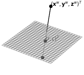
qi=(rc) To understand how a camera captures a 3D point, we need to know how it projects this point onto a 2D image plane as
shown below.

A 3D point in the camera coordinate system, which is centred at the optical center of the image plane is projected
onto the image plane as follows.
qc=(uv)=zcf(xcyc) Note both coordinate vectors and the focal length f are metric. The x,y,z point is the 3D location in space relative
to the camera. The coordinates u and v indicate the metric coordinates of the pixel of the image sensor. To further
convert u and v into pixel row and column coordinates (r,c), typically seen in images, one has to consider the
sensor geometry. In this equation the image sensor is characterized by the pixel size S and the image center
coordinates C.
qi=(rc)=zcf(Syv+CySxu+Cx) Typically, the world’s coordinate system does not align with the camera’s optical center. To project a point from the
world coordinate system into the optical center, we need to use a homography, a transformation that aligns these
coordinate systems, as follows.
pc=Hωc⋅pω A practical example could be locating objects on a conveyor belt. It makes practical sense to set up the world coordinate
system with reference to the conveyor belt rather than use the camera coordinate system.
Lenses are often not ideal and introduce distortions to the image coordinates, which need to be corrected for accurate
measurements. A common distortion model used by many lenses is the polynomial distortion model which models distortions
as radial and decentering. Without going into too much detail the radial distortion can be modeled by 3 K coefficients
and the decentering distortion by 2 P coefficients. The model cannot be analytically inverted so all projective points
cannot be computed from the distorted image plane and instead have to be computed from a corrected “undistorted”
image plane. That in summary leaves the following coordinate transformations to convert from 3D world coordinates
into pixel coordinates.
- 3D world coordinates to 3D camera coordinates
- 3D camera coordinates to 2D image plane coordinates
- Correcting image plane coordinates for lens distortion
- Image plane coordinates to pixel coordinates
pω→1pc→2qc→3qc~→4qi Camera calibration is vital for translating the 3D world into accurate 2D images. It corrects distortions, aligns world
and camera coordinates, and ensures that measurements taken from images are precise and reliable.
Stay tuned for our next blog that shows hands-on calibration of the Bottlenose camera in HALCON.
Cross-posted from my company blog.
Published: 2024-05-22
Updated : 2025-10-04
Not a spam bot? Want to leave comments or provide editorial guidance? Please click any
of the social links below and make an effort to connect. I promise I read all messages and
will respond at my choosing.