This article is written in support of the timer delay tool I wrote for the MCS-51 series. Most of the MCS-51 (8051)
derivatives have a similar architecture when it comes to timers, so this article should be applicable to most
of them. This assumes a basic understanding of the MCS-51 architecture and interrupt processing.
What is a Timer ?
This is a silicon block inside the microcontroller that can be sued to measure time, count events, or generate periodic events.
By offloading this function from the CPU, the microcontroller can perform other tasks while the timer operates independently.
Several events can be mapped to the timer, such as generating interrupts when a certain time has elapsed or toggling output pins
at specific intervals.
- Interval timing: When configured as a timer, the peripheral counts internal, machine-generated clock pulses of a
known period. This allows for the creation of precise time delays, a requirement for tasks such as debouncing switches,
controlling the blink rate of an LED, or establishing the timing for communication protocols.
- Event counting: hen configured as a counter, the peripheral increments its value in response to an external signal,
for example a falling edge on a specific input pin. This enables the microcontroller to count external occurrences
without constant CPU intervention, such as tracking objects on a conveyor belt, measuring rotations of a shaft via
an encoder, or counting pulses from a sensor.
- Periodic Signal Generation: By repeatedly timing out at a fixed interval, timers can be used to generate periodic
waveforms. This is the basis for creating Pulse Width Modulation (PWM) signals to control the speed of DC motors or
the brightness of LEDs, as well as for generating the stable clock required for serial communication baud rates.
The implementation of timers varies between different MCS-51 derivatives, but most of them share the basic two timers.
Their implementation is incredibly simple compared to modern microcontrollers, which often have multiple timers with various modes and
features. The MCS-51 timers are essentially just counters that increment based on the system clock or an external signal.
Given that die features were limited when the MCS-51 was designed, this simplicity was a necessity, and you are left
with just 8 and 16-bit timer modes. Most modern derivatives implement separate timer/counter peripherals that have
more advanced features. However, the details are very implementation specific and beyond the scope of this article.
The classic NMOS MCS-51 implementation uses a 12-clock (12T) cycle machine cycle, meaning that the timer increments every 12
oscillator cycles when configured as a timer.
Ttick=Fosc12 So if the external oscillator frequency is 11.0592 MHz, the timer tick period is approximately 1.085 µs. Modern CMOS
implementations often use a 6-clock cycle machine cycle (6T), effectively doubling the timer resolution for the
same oscillator frequency, or even a 1-clock cycle machine cycle (1T), which further increases the resolution. These
modes often are selectable via configuration bits or fuses during programming.
Timer 0, Timer 1
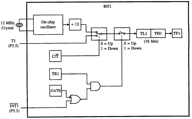
The original MCS-51 architecture includes two timers, Timer 0 and Timer 1, which can be configured as either timers or counters.
These two timers are 16-bit wide, meaning they can count from 0 to 65535 (0x0000 to 0xFFFF). Each timer has its own control
registers and can operate independently of each other. These special function registers (SFRs) are TL0/TH0 for Timer 0 and TL1/TH1 for Timer 1, where TLx is the low byte and THx is the high byte of the timer.
Timer vs Counter
The functional duality of the peripherals is controlled by the Counter/Timer (C/T) select bit within the Timer Mode (TMOD) register.
- When the
C/T bit is cleared (0), the timer operates in timer mode, incrementing based on the tick. - When the
C/T bit is set (1), the timer operates in counter mode, incrementing based on external events.
Pretty much all MCS-51 derivatives map the external pins onto Port 3. The T0 input is located on pin P3.4,
and the T1 input is on pin P3.5. The hardware samples the state of these pins once every machine cycle (note 1T, 6T, 12T differences).
So for a 12T to reliably detect a falling edge, the logic must sample a high level in one cycle and a low level in the
next. Consequently, the maximum external event counting rate is half the machine cycle frequency, or Fosc/24.
Register Control
Both timers are controlled via the TMOD and TCON registers. The TMOD register configures the mode of operation for both timers,
the upper nibble (bit 4-7) for Timer 1 and the lower nibble (bit 0-3) for Timer 0.
The TCON register contains control bits for starting and stopping the timers, as well as flags for timer overflows.
Since the timers are simple and registers take expensive silicon real estate, the lower nibble of the TCON register
is actually (ab)used for external interrupt control. The relevant bits for the timers are as follows:
Timer Modes
Each timer can be configured to operate in one of four modes, determined by the mode bits (M1 and M2) in the TMOD register:
- Mode 0 (13-bit Timer/Counter): In this mode, the timer operates as a 13-bit counter. The lower 5 bits of the high byte are
ignored, effectively limiting the count range to
0x0000 to 0x1FFF (8192 counts). This mode is rarely used. This is a
legacy mode from the earlier 8048 microcontroller. - Mode 1 (16-bit Timer/Counter): This is the most commonly used mode, where the timer functions as a full 16-bit counter,
counting from
0x0000 to 0xFFFF (65536 counts). When the timer overflows, it sets the corresponding overflow flag (TFx)
in the TCON register. - Mode 2 (8-bit Auto-Reload): In this mode, the timer operates as an 8-bit counter. When it overflows from
0xFF to 0x00,
it automatically reloads the value from the high byte register (THx). This mode is useful for generating precise time intervals. - Mode 3 (Split Timer Mode): This mode allows Timer 0 to be split into two separate 8-bit timers, effectively creating
two independent timers (Timer 0 low byte and Timer 0 high byte). Timer 1 remains unaffected and continues to operate in its
selected mode.
Mode 0: 13-Bit Timer/Counter
Mode 0 is a legacy configuration designed for backward compatibility with the earlier Intel MCS-48 microcontroller family.
- Structure: It configures the timer as a 13-bit up-counter. This is achieved by using all 8 bits of the high-byte
register (THx) and only the lower 5 bits of the low-byte register (TLx). The upper 3 bits of TLx are unused and
should be ignored.
- Operation: The 5-bit TLx register counts from 0 to 31. When it overflows from 31 back to 0, it
increments the 8-bit THx register. The main timer overflow flag (TFx) is set only when THx overflows from 255 to 0.
The total counting range is 213, or 8192 ticks.
- Use Case: Due to its limited counting range and the availability of the more versatile Mode 1, Mode 0 is
rarely employed in modern 8051 designs. Its primary purpose was to ease the migration of code from older platforms.
It can still be used for generating very short, repetitive time intervals where a 16-bit range is unnecessary.
Mode 1: 16-Bit Timer/Counter
Mode 1 is the most widely used and straightforward timer mode, functioning as a full 16-bit up-counter.
- Structure: This mode utilizes the full 16-bit capacity by cascading the
THx and TLx registers. - Operation: The
TLx register increments with each timer tick. When TLx overflows from 255 (0xFF) to 0, it
carries over and increments the THx register. The timer overflow flag, TFx, is set by the hardware only when the
THx register overflows, which signifies that the entire 16-bit value has rolled over from 65,535 (0xFFFF) to 0. - Use Case: Mode 1 is the workhorse for general-purpose timing applications. Its extensive range of
65,536 counts allows for the creation of substantial time delays. For instance, with an 11.0592 MHz crystal,
a single overflow can generate a maximum delay of 65,536×1.085μs≈71.1 ms.
Longer delays are easily achieved by using a software loop to count multiple overflows. This mode is the
default choice for creating custom delay subroutines and measuring the duration of events.
Mode 2: 8-Bit Auto-Reload
Mode 2 provides a highly efficient mechanism for creating fixed-period events by implementing an 8-bit timer with a
hardware-based auto-reload feature.
- Structure: In this mode, the TLx register serves as the 8-bit up-counter, while the THx register acts as a
read-only buffer, holding the reload value.
- Operation: The TLx register is initialized and begins counting up. When TLx overflows from 255 (
0xFF) to 0,
two actions occur simultaneously in hardware: the TFx flag is set, and the value stored in THx is automatically
copied back into TLx. The value in THx remains unchanged throughout this process. - Use Case: This mode is ideal for applications that require a continuous stream of periodic interrupts without
the software overhead of manually reloading the timer registers in an interrupt service routine. Its most critical
and widespread application is UART baud rate generation. By setting Timer 1 to Mode 2 and loading TH1 with the
appropriate value, a stable and precise clock source can be generated for the serial communication peripheral,
enabling reliable data transfer at standard baud rates. It is also highly effective for generating high-frequency
PWM signals where the period is fixed and short.
Mode 3: Split Timer Mode
Mode 3 is a unique and specialized mode that applies exclusively to Timer 0, effectively splitting its 16-bit
register into two independent 8-bit timers. When TMOD is configured for Timer 0 in Mode 3, the single timer peripheral
is reconfigured as follows:
TL0 becomes an 8-bit timer/counter that is controlled by the standard Timer 0 control bits: TR0 (to start/stop) and TF0 (the overflow flag).
It can be configured as a timer or counter using the C/T bit and can be hardware-gated using the GATE bit and the INT0 pin.TH0: Becomes a separate, independent 8-bit timer (it cannot be used as an event counter). It ingeniously
“borrows” the control logic from Timer 1. It is started and stopped by the TR1 bit and sets the TF1 flag upon overflow.- While Timer 0 is operating in Mode 3, the standard Timer 1 is rendered largely uncontrollable. Since its run-control bit
(
TR1) and overflow flag (TF1) have been co-opted by TH0, Timer 1 cannot be started, stopped, or generate an
interrupt through its normal mechanism. However, the Timer 1 register pair (TH1/TL1) continues to increment on
every machine cycle if configured in a timer mode.
The free-running Timer 1 can still be used for tasks that do not require interrupts or precise start/stop control.
The most common scenario is to configure Timer 1 in Mode 2 to serve as the dedicated baud rate generator for the serial
port, which only requires a continuous clock source.
This “hack” allows an 8051, a device with only two physical timer blocks, to function as if it has three.
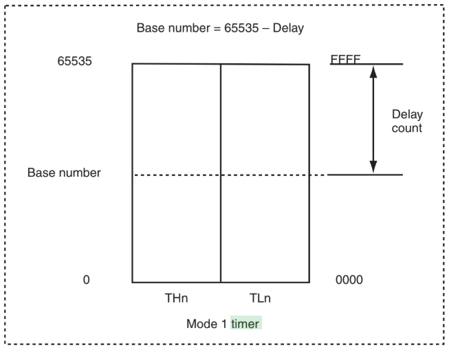
Delay Setting
Consider mode 1 (16-bit timer) with an 11.0592 MHz crystal on a 12T 8051. The timer tick period is approximately 1.085 µs.
Ttick=11.0592×10612≈1.085μs To create a delay of 50 ms, we need to determine how many timer ticks are required:
N=1.085×10⁻⁶s50×10−3s≈46081 ticks The issue is that the timer counts up from 0x0000 to 0xFFFF (65535), so we need to calculate the initial value to
load into the timer registers:
Initial Value=65536−46081=19455 As illustrated below
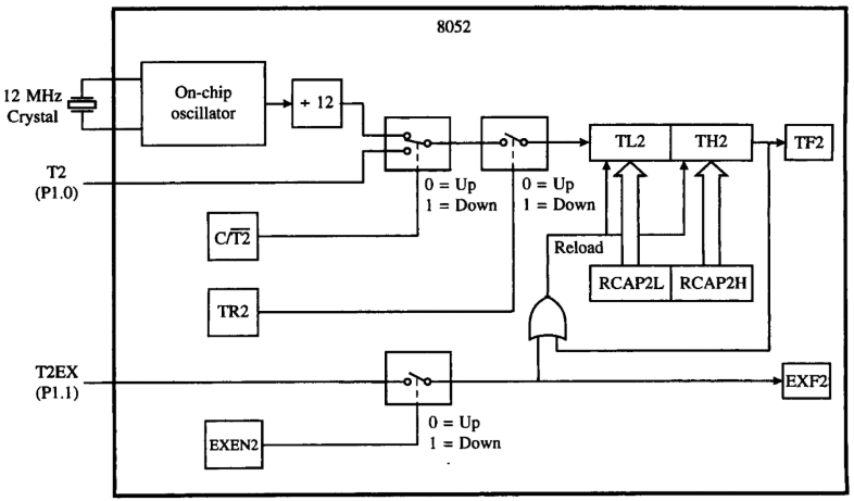
The 8052’s Timer 2
The 8052 variant adds a third timer, Timer 2, which offers additional features and modes of operation, that is also
implemented in many modern derivatives such as the STC89C52 and the NXP P89V51RD2. Timer 2 offers more advanced
functionality, including auto-reload and capture modes, making it suitable for more complex timing tasks like PWM
generation and input-signal measurement. This timer is controlled by its own set of dedicated SFRs.
T2CON: The main, bit-addressable control register for Timer 2.T2MOD: A non-bit-addressable register that configures additional modes for Timer 2.TH2 and TL2: The high and low byte registers for Timer 2.RCAP2H and RCAP2L: The high and low byte registers for Timer
The TMOD2 register has the following relevant bits:
In Auto-Reload Mode, upon a timer overflow, the 16-bit value stored in (RCAP2H, RCAP2L) is automatically loaded into the
timer registers (TH2, TL2). In Capture Mode, an event on the T2EX pin triggers the hardware to copy the current value from (TH2, TL2) into
(RCAP2H, RCAP2L).
So from the flags we can identify the following modes of operation:
Capture mode has two variants. If EXEN2 is cleared, the timer is a 16-bit timer or counter that sets TF2 on overflow.
If EXEN2 is set, a falling edge on the T2EX pin (P1.1) causes the current timer value TH2 and TL2 to be latched into the RCAP2H and RCAP2L registers, and the EXF2 flag is set. This mode is useful for measuring the time between external events.
In auto-reload mode, when the timer overflows from 0xFFFF to 0x0000, the value in RCAP2H and RCAP2L is automatically
loaded into TH2 and TL2. This mode is often used for generating periodic interrupts. Further, DCEN can be set to make the timer count down
instead of up.
If EXEN2 is set, then a reload can be triggered either by an overflow or by a falling edge at input T2EX.
Baud rate generation is enabled by setting either RCLK or TCLK. In this mode, Timer 2 operates as a 16-bit auto-reload timer,
but the overflow is used to clock the UART receiver or transmitter. This allows for flexible baud rate generation independent of the main system clock,
as explained in the next article.
From the opening quote, lets hope you don’t miss the timer interrupts of your life!
I plan to post more on peripheral interrupts (serial ports, etc.) in future articles, and then wrap it all up with
a comprehensive project.
Good references for further reading:
Published: 2025-10-27
Updated : 2025-10-27
Not a spam bot? Want to leave comments or provide editorial guidance? Please click any
of the social links below and make an effort to connect. I promise I read all messages and
will respond at my choosing.