So far we have covered basic MCS-51 programming and interfacing with simple buttons, button matrices, and various types of
displays. In this installment, we will explore rotary encoders and stepper motors, which are used in various applications such as
volume controls, menu navigation, and precise positioning systems.
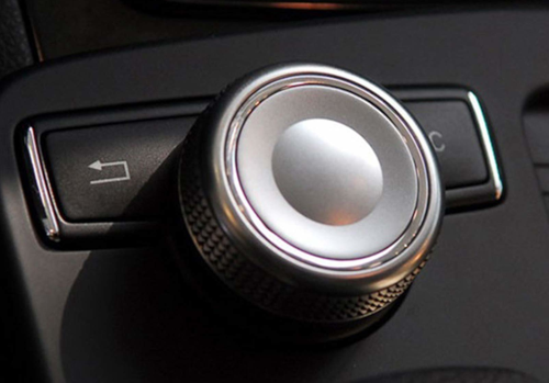
This type of interface has made it to many vehicles, such as the BMW iDrive system or Mercedes knob control interface that came out with the W204
series (shown above). It is surprising how pervasive they have become since the early 2000s. It is one of these adjacent
possible inventions that could have been done in the 1980s but was not, until the right mix of technology and need came together.
The objective is to control a stepper motor’s position with a rotary knob: turn the knob, and the shaft follows by the
same angle.
Unfortunately, my HC6800-ES development board did not have a rotary encoder pre-soldered and did not ship with a stepper
motor. However, they included a Darlington array (ULN2003) that can be used to drive a unipolar stepper motor. Note
that stepper motors with only two coils (bipolar) need an H-bridge driver, which is a bit more complex to implement.
Rotary Encoder Knobs
Looking at the datasheet of the encoder knob module, we can see that it has
three pins: A, B, and C (common ground). The A and B pins are connected to the two output channels of the rotary encoder,
which generate quadrature signals as the knob is rotated. The C pin is connected to ground. Independently, the encoder
also has a built-in push button that can be used for additional functionality.
The pattern of the signals on pins A and B can be used to determine the direction of rotation. It is called quadrature encoding
because the two signals are 90 degrees out of phase. By monitoring the transitions of these signals, we can determine whether the knob
is being turned clockwise or counterclockwise. The following table summarizes the state transitions for clockwise and counterclockwise rotation:
By tracking the changes in the states of pins A and B, we can determine the direction of rotation and
increment or decrement a counter accordingly. So if B changes first, we are turning clockwise, otherwise counterclockwise.
Another simplification is to just sample the state of A (CLK) and look at B (DT) to determine the direction. If for
any transition of A from high to low, B is high, then we are turning counterclockwise, otherwise clockwise. This
simplifies the code, but now we need at least two transitions per step to register a change.
When the button is pressed, it connects the C pin to ground, which can be detected by monitoring the state of the button pin.
Depending on what module you get, the pins may already have pull-up resistors built-in.
We can connect the A and B pins to two GPIO pins configured as inputs. We can use
interrupts or polling to monitor the state changes of these pins. To help with debouncing it may be best to sample
the state from a timer interrupt at a regular interval, say every 1ms, or artificially slow down the reading loop.
Let’s start with a simple example that lights up the LEDs D1 - D8 on the HC6800-ES board to indicate the direction of rotation.
When turned clockwise, we will light up D1 to D8 in sequence, and when turned counterclockwise, we will light them down in reverse sequence.
While the button is pressed, we will disable the LED updates. Given the lack of an onboard rotary encoder, I used the ISP1
header to connect one. I connected 5V to +, GND to GND, A to P1.7 (CLK), B to P1.6 (DT), and the button to P1.5 (SW).
Note the buzzer is also connected to P1.5, so you will hear clicks when you press the button.
#include <mcs51/8051.h>
#include <mcs51/compiler.h>
#include <stdint.h>
#define SW P1_5
#define DT P1_6
#define CLK P1_7
#define LED P2
void delay(uint16_t t) {
while (t--)
;
}
void main(void) {
SW = 1;
DT = 1;
CLK = 1;
__bit last_clk = 1;
uint8_t count = 0;
for(;;) {
__bit clk = CLK;
if(last_clk == 1 && clk == 0) {
if(DT == 0) {
if(count < 7) {
count++;
} else {
count = 0;
}
} else {
if(count > 0) {
count--;
} else {
count = 7;
}
}
}
last_clk = clk;
if(SW == 0) {
LED = 0xFF;
while(SW == 0);
} else {
LED = ~(1 << count);
}
delay(1000);
}
}
The end result looks as follows:
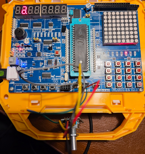
The full example is 05_enc.
Stepper Motor Control
A stepper motor is a type of brushless DC motor that divides a full rotation into a number of equal steps. The motor’s
position can be controlled precisely without the need for feedback systems, making it ideal for applications requiring
accurate positioning.
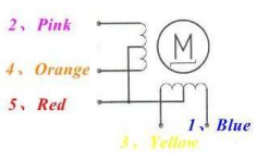
A staple for recent embedded and RC projects is the 28BYJ-48 stepper motor, which is small, inexpensive and runs on 5V. It is a unipolar stepper motor with 5 wires:
- Red: Common wire (connected to Vcc)
- Orange: Coil 4
- Yellow: Coil 3
- Pink: Coil 2
- Blue: Coil 1
The numbering is the datasheet’s, and the list is in the order the wires leave the plug. That order is also the order
in which the coils have to fire, which matters in a moment.
The idea is to energize the coils in a specific sequence to make the motor shaft rotate. The most common driving methods are:
- Full Step: One phase mode, energizing one coil at a time.
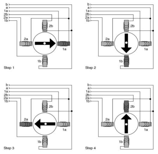
- Full Step: Two phase mode, energizing two coils at a time for higher torque.
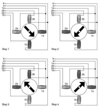
- Half Step: Alternating between energizing one and two coils for smoother motion and higher precision (at the loss of torque).
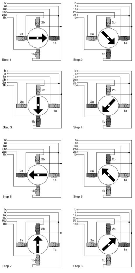
Atmel (ehm Microchip) has a good
application note on stepper motor control that goes into more detail. They wire up 12V steppers directly with a discrete
transistor circuit and explicit protection, but for our small stepper motor the ULN2003 Darlington array on the HC6800-ES board
will do just fine.
Wiring the motor
The ULN2003 inputs IN1 to IN4 are wired to P1.0 to P1.3, and its outputs OUT1 to OUT4 go to the 5-pin
header P3 next to the chip, marked + A B C D on the silkscreen. The first pin is VCC. The motor’s JST plug goes
straight on with the red wire on +, which puts orange, yellow, pink and blue on A to D. Because the plug already
carries the coils in firing order, A to D follow P1.0 to P1.3 without any rearranging. If a motor only hums,
two phases are out of order, and the cheap fix is to swap two entries in software rather than re-pin a crimped plug.
The ULN2003 does not invert: writing a 1 to an input energizes the matching coil. It is also the reason the chip is
on the board at all. A coil of the 5V motor is about 50 ohm, so it draws around 100 mA, and an 8051 pin can source a
fraction of a milliamp.
Half-stepping in a table
The three diagrams above collapse into one table of eight entries. Each entry energizes one coil or two neighbours, and
consecutive entries differ by exactly one coil.
static const uint8_t half_step[8] = {
  0x01, 0x03, 0x02, 0x06, 0x04, 0x0C, 0x08, 0x09
};
Walking the index forward turns the shaft one way, walking it backward turns it the other. Through its roughly 64:1
gearbox, the 28BYJ-48 needs 4096 of these half-steps for one turn of the output shaft.
Why the polling loop stops working
The encoder demo above polls the knob in a loop, with a busy-wait delay as its debounce. That is fine for LEDs. It falls
apart the moment the same loop also has to step a motor, because every step needs a delay of its own, and while the CPU
sits in that delay nobody is watching the knob. Turn it quickly and detents go missing.
The fix is to hand both jobs to one timer. Timer 0 fires every millisecond. On this board’s 12 MHz crystal one machine
cycle is exactly 1 µs, so the reload value is simply 65536 - 1000. Every tick samples the encoder, every second tick
moves the motor one half-step towards its target, and the main loop does nothing but copy the count onto the LEDs.
Sampling on a fixed tick also replaces the debounce delay. Instead of waiting for one falling edge, the decoder uses the
full transition table from earlier and counts plus or minus one per transition. It only commits a detent when the knob
settles back at rest with at least half a cycle accumulated. Contact bounce looks like +1 -1 +1 -1, and it nets out to
nothing.
void timer0_isr(void) __interrupt(TF0_VECTOR) {
int8_t d;
timer0_reload();
d = quad_detent(&quad, AB(CLK, DT));
if (d && detents + d <= DETENT_LIMIT && detents + d >= -DETENT_LIMIT) {
detents += d;
target = (int16_t)(((int32_t)detents * HALF_STEPS_PER_REV) / DETENTS_PER_REV);
}
if (++step_div < STEP_TICKS) {
return;
}
step_div = 0;
if (position != target) {
position += (target > position) ? 1 : -1;
P1 = P1_INPUTS | stepper_phase((uint8_t)position);
idle = 0;
} else if (idle < IDLE_TICKS / STEP_TICKS) {
if (++idle == IDLE_TICKS / STEP_TICKS) {
P1 = P1_INPUTS;
}
}
}
P1_INPUTS is 0xF0. It keeps the upper four latches high on every write, so the encoder lines on P1.5 to P1.7 stay pulled up while the lower nibble drives the motor.
Two clicks per step
The first run on the real board worked, except that the shaft only moved on every second click of the knob.
The decoder committed a detent when the knob came back to rest with both lines high, which is where the common KY-040
sits between clicks. My module clicks twice as often. It rests with both lines high, then with both lines low, then high
again, so a click is half a quadrature cycle, not a whole one. Half the clicks ended at a rest position the decoder did
not recognise.
From the outside the two kinds of module look identical. The fix is a flag: in half-cycle mode
both rest positions count, and two transitions in the same direction make a click. The simple falling-edge method from
the encoder section has the same blind spot. That is what the line about needing two transitions per step was quietly
admitting.
One knob turn, one shaft turn
With every click counted, the shaft overturned the knob. I had assumed 20 clicks per revolution, the usual figure.
Counting them on the knob gave 30.
The motor wants 4096 half-steps per revolution, so a click is 136.53 half-steps, which is not a whole number. Adding 137
on every click walks the shaft half a half-step further from the knob each time, and 136 drifts the other way.
So the target is never accumulated. It is recomputed from the click count every time, multiplying first and dividing
last. Thirty clicks land on exactly 4096 half-steps, and the error never exceeds one half-step however long the knob is
turned. Multiply first, divide last, and never add up a rounded number.
The product needs 32 bits, because 150 clicks is already 20480 half-steps. The count is clamped at 150 in either
direction, five turns of the shaft, so the 16-bit target cannot wrap round.
Once the motor reaches its target, the coils stay energized and hold the shaft against nothing. A held half-step costs
100 to 200 mA, and all of it turns into heat. The gearbox holds the shaft well enough on its own, so after 200 ms at
rest the interrupt switches all four outputs off.
Pressing the knob sets the current position as the new zero, without moving the shaft.
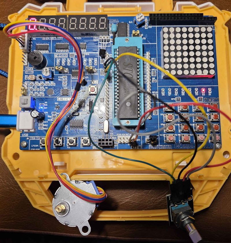
Mark the knob and the shaft, turn the knob a full turn either way, and the two marks line up again. The motor runs at
500 half-steps per second, about seven turns a minute, so a fast spin of the knob queues up a target and the shaft
follows a moment later. The LEDs count the clicks, which made the two-clicks problem obvious long before the arithmetic
was right.
The full example is 05_enc_stepper. The logic
that decides what a click is lives in its own file, logic.c, apart from the timer and the pins, because the knob was
the part that was wrong twice.
It is a long way from iDrive, but it is the same idea: a knob that counts clicks, and something on the far side that
trusts the count. Getting the count right was the whole job.
Published: 2025-11-20
Updated : 2026-10-06
Not a spam bot? Want to leave comments or provide editorial guidance? Please click any of the social
links below and make an effort to connect. I promise I read all messages and will respond at my
choosing.