After having the tools for peripherals bagged in the previous posts (UART, Timers, Interrupts, and GPIOs), and having a basic understanding of how to code for the MCS-51
series works internally and externally, it’s time to get into some real-world
interfacing.
Before the age of pervasive cell phones and widget connectivity, user interfaces had to be realized as part of the
embedded system itself. This means that the embedded system had to provide a way for users to interact with it
directly, without relying on external devices or networks. This often involved using simple input and output
devices, such as buttons, switches, LEDs, and displays. These days we often take for granted the rich user
interfaces provided by modern devices, but in the early days of embedded systems, user interfaces were often
limited to simple LED indicators and basic input devices. The graduation project that the typical embedded designer
finished in the day was to interface a HEX-keypad and an array of 7-segment displays to an MCS-51 microcontroller (with
minimal external circuity).
These days such interfaces are confined to public appliances or items were not connected (even though this is changing right now). This post will cover
And then dive into adapting existing libraries for more complex interfacing needs. We then
conclude with multiplexing techniques to expand the number of buttons and LEDs that can be interfaced using limited GPIO pins.
LEDs
LEDs (Light Emitting Diodes) are one of the simplest and most common output devices used in embedded systems.
They are used to indicate the status of the system, provide feedback to the user, or simply to add visual interest to the
system. LEDs are typically connected to the microcontroller’s GPIO pins, and can be controlled using simple
digital output commands. The issue though for the MCS-51 series is that the GPIO pins can only source or sink a limited amount of current.
To circumvent this, you can use transistors or logic buffers to drive the LEDs.
If you drive LEDs from an GPIO pin or a buffered logic gate, you need to ensure that the current flowing through the LED does not exceed its maximum rating.
Typically, this is done by adding a current-limiting resistor in series with the LED. The value of the resistor can be calculated using Ohm’s law:
RLED=ILEDVsupply−VLEDΩ Where Vsupply is the supply voltage, VLED is the forward voltage drop of the LED, and ILED is the desired current through the LED. Consider a simple example, where the LED is a red LED with
a forward voltage of 1.95 V, a current rating of 5 mA, and the MCS-51 supply voltage is 5 V. The resistor value would be:
RLED=0.005A5V−1.95V=610Ω This means that a resistor of approximately 610 Ω should be used in series with the LED to limit the current to 5 mA.
That value is out of bounds for most classic MCS-51 derivatives. You need to find a circuit that buffers the GPIO pin
and can source/sink more current. A simple NPN transistor circuit can be used to drive an LED from a GPIO pin. However,
to limit placements and accounting for the fact that you probably need more current driving for other peripherals,
you can use a logic buffer IC, such as the 74540 or an
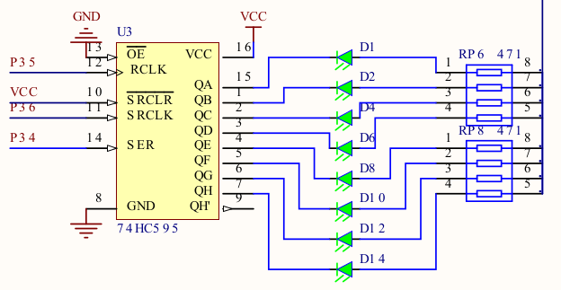
8-bit shift register, such as the 74HC595. Consider the 74LS family for a more current capability. Be sure to check against the
datasheet of the specific IC you are using to ensure that it can handle the current requirements of your application.
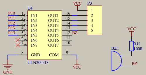
To drive larger loads consider Darlington transistor arrays, such as the ULN2003A or ULN2803A. When you exhaust this go to dedicated LED driver ICs,
or transistor arrays or individual transistors.
The circuits look as follows:
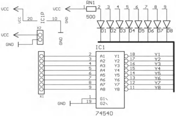
The drawback of the buffer is that you consume quite a few number of precious GPIO pins. The shift register
only needs three GPIO pins (Data, Clock, and Latch) to control 8 output and frees up more GPIO pins for other uses.
Buttons are one of the most common input devices used in embedded systems. They are used to allow users to interact
with the system, provide input, or trigger specific actions. Buttons are typically connected to the microcontroller’s
GPIO pins, and can be read using simple digital input commands. However, buttons are mechanical devices
and can produce noise or “bounce” when pressed or released. This can lead to multiple readings being registered for a
single button press, which can cause issues in the system. To mitigate this, a technique called “debouncing” is used. Debouncing can be
implemented in hardware or software. Hardware debouncing typically involves adding a capacitor and resistor to the
button circuit to filter out the noise, however, this can add complexity and cost to the system. Software debouncing is often preferred, as it can be
easily implemented in the microcontroller’s firmware.
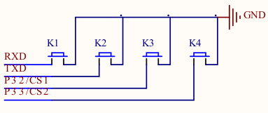
The same issue of conserving GPIO pins applies here too, so to entertain multiple buttons, you can use a matrix
configuration. In a matrix configuration, buttons are arranged in rows and columns, and each button is connected to a
unique combination of row and column lines. This allows multiple buttons to be read using a
smaller number of GPIO pins as shown below.
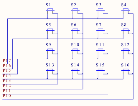
The scanning process involves setting one row line to a low state and reading the column lines to see if any buttons
in that row are pressed. This process is repeated for each row line, allowing all buttons in the matrix to be read using a
smaller number of GPIO pins. That scanning pattern also solves the debouncing issue, as each button in the matrix is only
read once per scan cycle. The drawback of the matrix configuration is that the number of simultaneous button presses is limited
by the number of rows and columns in the matrix. If multiple buttons in the same row or column are pressed at the same time,
it can lead to “ghosting” or “masking” issues, where the microcontroller cannot accurately determine which buttons are pressed.
Buzzers
Buzzers are simple audio output devices used in embedded systems to provide audible feedback to users. They are often
used to indicate the status of the system, provide alerts or warnings, or simply to add sound effects to the system.
Buzzers suffer from the same current sourcing/sinking issues as LEDs, so consider using a buffer or transistor array to drive them.
The added complication is that buzzers need to be driven with a square wave signal to produce sound. This can be achieved using
the microcontroller’s GPIO pins and a timer or PWM (Pulse Width Modulation) module.
If you use speakers instead of buzzers, you also need to account for the inductive kickback that the speaker coil
produces. This can be mitigated by adding a flyback diode across the speaker terminals to protect the driving circuit,
or using a Darlington transistor array like the ULN2003A or ULN2803A.
Simple Polling Example
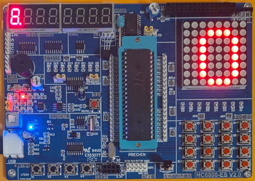
Here is a simple example of how to interface buttons and LEDs using polling. In this example, we will use a button
to toggle LEDs on and off. For starters lets use the buttons directly. On the HC6800-ES board, the buttons are connected P3.0 to P3.3, and the LEDs are connected to P2.0 to P2.7.

The LEDs are active low, so writing a 0 to the corresponding bit in P2 will turn on the LED, while writing a 1 will turn it off.
Since the buttons are also active low, we need to check for a 0 when reading the button state.
Note the development kit has pull-up resistors on any I/O pin, so the button pins will read 1 when not pressed and 0 when pressed.
#include <mcs51/8051.h>
void main(void) {
for(;;) {
P2_0 = P3_1;
P2_1 = P3_0;
P2_2 = P3_2;
P2_3 = P3_3;
}
}
The end result looks like this:
See GitHub for the full code.
State Toggling Example
Now one of the issues with the above example is that the LED will only be on while the button is pressed. To toggle the LED state on each button press,
we need to implement a simple state machine and also worry about the debouncing issue. A simple improvement is to
only toggle the LEDs and sample the buttons at a fixed interval, say every 50 ms. This can be achieved using a timer interrupt.
So using the Timer Delay Tool we obtain the following configuration for Timer 0:
12 MHz clock- Mode 1 (16-bit)
50 ms delay12T mode
void timer0_init(void) {
TMOD &= 0xF0;
TMOD |= 0x1;
TH0 = 0x3c;
TL0 = 0xb0;
TF0 = 0;
TR0 = 1;
}
To use the interrupt we need to enable global and Timer 0 interrupts:
EA = 1;
ET0 = 1;
Working this into a state variable and toggling the LED state on each button press, we obtain the following code:
__bit led_0_state = 0;
__bit led_1_state = 0;
__bit led_2_state = 0;
__bit led_3_state = 0;
void tf0_isr(void) __interrupt(TF0_VECTOR) {
if(P3_1 == 0) {
led_0_state = !led_0_state;
}
if(P3_0 == 0) {
led_1_state = !led_1_state;
}
if(P3_2 == 0) {
led_2_state = !led_2_state;
}
if(P3_3 == 0) {
led_3_state = !led_3_state;
}
P2_0 = led_0_state;
P2_1 = led_1_state;
P2_2 = led_2_state;
P2_3 = led_3_state;
TF0 = 0;
}
Now one of the drawbacks of this approach is that if the button is held down, the LED will keep toggling on and off in 50 ms intervals.
The end result looks like this:
See GitHub for the full code.
Adding Debouncing
To mitigate this, we can implement a simple debouncing mechanism. Since we already have a timer interrupt running at 50 ms intervals,
we can use a simple counter to track how long the button has been pressed. If the button is pressed for more than 1000 ms, we can consider it a valid press and toggle the LED state. This way, if the button is held down, the LED will only toggle once
per second. To ensure that the system is responsive to quick button presses, we have to start the button sampling at
the beginning of the debouncing period, rather than letting the counter expire first.
__bit led_0_state = 0;
unsigned char button_0_counter = 0;
__bit led_1_state = 0;
unsigned char button_1_counter = 0;
__bit led_2_state = 0;
unsigned char button_2_counter = 0;
__bit led_3_state = 0;
unsigned char button_3_counter = 0;
void tf0_isr(void) __interrupt(TF0_VECTOR) {
if(button_0_counter) {
button_0_counter++;
if(button_0_counter >= 20)
button_0_counter = 0;
}
if(button_1_counter) {
button_1_counter++;
if (button_1_counter >= 20)
button_1_counter = 0;
}
if(button_2_counter) {
button_2_counter++;
if (button_2_counter >= 20)
button_2_counter = 0;
}
if(button_3_counter) {
button_3_counter++;
if (button_3_counter >= 20)
button_3_counter = 0;
}
if(P3_1 == 0 && button_0_counter == 0) {
led_0_state = !led_0_state;
button_0_counter++;
}
if(P3_0 == 0 && button_1_counter == 0) {
led_1_state = !led_1_state;
button_1_counter++;
}
if(P3_2 == 0 && button_2_counter == 0) {
led_2_state = !led_2_state;
button_2_counter++;
}
if(P3_3 == 0 && button_3_counter == 0) {
led_3_state = !led_3_state;
button_3_counter++;
}
P2_0 = led_0_state;
P2_1 = led_1_state;
P2_2 = led_2_state;
P2_3 = led_3_state;
TF0 = 0;
}
The end result looks like the previous example, but now the LEDs only toggle once per second when the button is held down.
See GitHub for the full code.
Buzzer Interfacing
For interfacing buzzers or speakers you may drive significant loads compared to LEDs. Consider using a dedicated driver IC or a Darlington transistor array
like the ULN2003A or ULN2803A to drive the buzzer. You can use the timer interrupt to generate a square wave signal to
drive the buzzer. The frequency of the square wave can be adjusted to produce different tones.
Say we want to generate a 500 Hz tone. With a 12 MHz clock and 12T mode, we need to toggle the buzzer pin every (12,000,000 / 12) / (2 * 500) = 1000 timer ticks. We can set up Timer 1 in mode 1 (16-bit) to generate an interrupt
every 1000 ticks, you can use the Timer Delay Tool to calculate the timer values.
12 MHz clock- Timer 0
- Mode 1 (16-bit)
1 ms delay12T mode
The resulting timer initialization is 0xFC18, which works out to 1000 ticks by 0x10000 - 0xFC18 = 0x03E8 = 1000.
void timer0_init(void) {
TMOD &= 0xF0;
TMOD |= 0x1;
TH0 = 0xFC;
TL0 = 0x18;
TF0 = 0;
TR0 = 1;
}
void main(void) {
timer0_init();
ET0 = 1;
EA = 1;
for(;;);
}
__bit buzzer_state = 0;
void tf0_isr(void) __interrupt(TF0_VECTOR) {
P2_0 = P3_2;
if(P3_3 == 0) {
buzzer_state = !buzzer_state;
}
P1_5 = buzzer_state;
TH0 = 0xFC;
TL0 = 0x18;
TF0 = 0;
}
The end result looks like this:
See GitHub for the full code.
While the above examples are simple and straightforward, they do not scale well for larger applications. For more complex
applications, it is often better to use existing libraries that provide more advanced functionality and features.
While there is a lot of work on the Arduino Side to provide libraries for the latest gimmick, in terms of pure C libraries
that can be easily adapted to the MCS-51 series, there is not much out there that is generic enough to be used across different
platforms. One of the libraries that stands out is the Button Library by LibDriver,
which provides a simple and easy-to-use interface for interfacing buttons in embedded systems and provides features such as debouncing,
long-press detection, and multi-click detection. The library is written in pure C and can be easily adapted to the MCS-51 series.
Their target examples focus on STM32 and higher-level Linux platforms, but the core logic can be adapted to the MCS-51 series with some effort.
However, the library relies on external interrupts that trigger on rising and falling edges, which the classic MCS-51
series does not support. This could be solved by using a timer interrupt to poll the button states at regular intervals,
similar to the examples above but that would already introduce a lot of changes to the library internals.
I would keep the button library in mind for modern MCS-51 derivatives that support external interrupts on GPIO pins on
rising and falling edges, such as the STC8H series.
As we see, if we were to add the UART functionality too, we would quickly run out of GPIO pins. To mitigate this,
we can use multiplexing techniques to share GPIO pins between multiple buttons and LEDs. This can be achieved using
shift registers, multiplexers, or other techniques. By multiplexing the buttons and LEDs, we can reduce the number of GPIO pins
required for interfacing, allowing us to add more functionality to the embedded system.
Multiplexing LEDs with Shift Registers
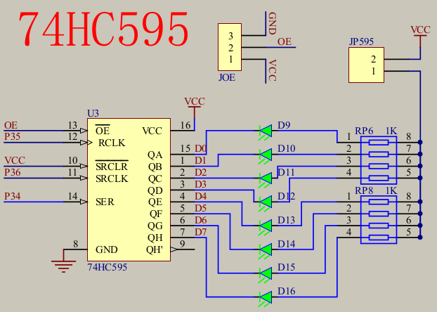
The simplest way to multiplex LEDs is to use a shift register, such as the 74HC595,
which allows us to control multiple LEDs using only a few GPIO pins. The shift register can be used to shift out the LED states
to the LEDs, allowing us to control multiple LEDs using only a few GPIO pins. Looking at the HC6800-ES board again, we can use P3.4 to P3.6 for the shift register control pins (SER, SRCLK, and RCLK).
SER Serial Data Input is the input pin where data is shifted in.SRCLK Shift Register Clock Input is the clock pin that shifts the data in on the rising edge.RCLK Register Clock Input is the latch pin that transfers the shifted data to the output pins on the rising edge.
The output enable pin (OE) can be tied to ground to always enable the outputs via JOE on the HC6800-ES board. To
provide the high-side voltage to the LEDs, jumper JP595.
The code to low a single byte to the shift register looks like this:
#include <mcs51/8051.h>
#include <mcs51/compiler.h>
#include <stdint.h>
#define SRCLK P3_6
#define RCLK P3_5
#define SER P3_4
void HC575_write(uint8_t value) {
SRCLK=0;
RCLK=0;
for(uint8_t i=0; i<8; i++) {
SER = value >> 7;
value <<= 1;
SRCLK = 1;
NOP();
NOP();
SRCLK = 0;
}
RCLK = 1;
NOP();
NOP();
RCLK = 0;
}
void main(void) {
for(;;) {
for(uint8_t i=0; i<8; i++) {
HC575_write(~(1 << i));
for(uint16_t j=0; j<30000; j++);
}
}
}
The end result looks like this:
See GitHub for the full code.
8x8 LED Matrix with Shift Registers
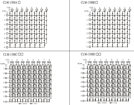
Another common UI element are LED matrices, which can be used to display characters, symbols, or simple graphics. LED matrices
can be driven using shift registers, multiplexers, or other techniques. As seen in the figure above, an 8x8 LED matrix consists of 8 rows and 8 columns of LEDs. To control the LEDs in the matrix, we need to set the appropriate row and column lines.
More advanced LED matrices also support bidirectional driving to show multiple colors, but for simplicity, we will focus on a single-color matrix.
The LED matrix implementation on the HC6800-ES board allegedly uses the 1588AS LED matrix. It is mounted rotated by 90° on the board,
so the rows and columns are swapped compared to the figure above.
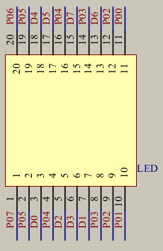
It is a little tricky to see from the HC6800-ES board, but in addition to the 8 individual LEDs D9 to D16, there is also
a 8x8 LED matrix connected to P0 (columns) and the outputs D0 - D7 (rows) via a 74HC595 shift register. To drive the LED matrix,
we need to multiplex the rows and columns. This can be achieved by setting the column data to the P0 port and shifting the row data
to the 74HC595 shift register.
For every row, we set the corresponding bit pattern to P0 and shift the row data to the shift register. At speed
this creates the illusion that all LEDs are lit at the same time. To illustrate the scanning pattern with artificially
slowed down timing, consider the following code:
#include <mcs51/8051.h>
#include <mcs51/compiler.h>
#include <stdint.h>
#define SRCLK P3_6
#define RCLK P3_5
#define SER P3_4
uint8_t matrix_rows[] = {
0b00000000,
0b00011100,
0b00100010,
0b00100010,
0b00100010,
0b00100010,
0b00100010,
0b00011100,
};
void HC575_write(uint8_t value) {
SRCLK=0;
RCLK=0;
for(uint8_t i=0; i<8; i++) {
SER = value >> 7;
value <<= 1;
SRCLK = 1;
NOP();
NOP();
SRCLK = 0;
}
RCLK = 1;
NOP();
NOP();
RCLK = 0;
}
void main(void) {
for(;;) {
P0 = 0xFF;
for(uint8_t i=0; i<8; i++) {
P0 = ~matrix_rows[i];
uint8_t scan_line = 7-i;
HC575_write((1 << scan_line));
HC575_write(0);
for(uint16_t j=0; j<30000; j++);
}
}
}
So the pattern looks as follows.
At speed (i.e. remove the delay loop), the zero appears solidly lit.
In addition to the loop implementation you could also migrate the scanning to a timer interrupt to free up the main loop
for other tasks. There is also room for improvement. If the OE pin of the 74HC595 were programmable, you would not
have to rely on shifting out a zero pattern to avoid ghosting. You would only need to shift one line at a time and
disable the outputs while changing the column data. This would make for a better implementation directly in the timer interrupt.
Matrix displays are an attractive way to provide a compact user interface with limited GPIO usage. As shown above
you can map characters and symbols to the matrix rows and display them by scanning through the rows. This process
is taken to the extreme with DOT-matrix and character LCDs, which use similar multiplexing techniques to display
more complex information and hide the scanning from the user. The character patterns are typically stored in flash
or an internal EEPROM and there is some extra programmable memory to load in custom characters.
See GitHub for the full code.
Similarly to the LED matrix, buttons can also be multiplexed using a matrix configuration. This allows multiple buttons
to be read using a smaller number of GPIO pins. The scanning process involves setting one row line to a low state and reading the
column lines to see if any buttons in that row are pressed. This process is repeated for each row line, allowing all buttons in the matrix to be read using
a smaller number of GPIO pins. The scanning pattern also solves the debouncing issue, as each button in the matrix is only
read once per scan cycle. The drawback of the matrix configuration is that the number of simultaneous button presses is limited
by the number of rows and columns in the matrix. If multiple buttons in the same row or column are pressed at the same time,
it can lead to “ghosting” or “masking” issues, where the microcontroller cannot accurately determine which buttons are pressed.
For the scanning routine, consider the following code. On the HC6800-ES board, the buttons are connected to P1.0 to P1.7. P1.0 to P1.3 are connected to the columns, and P1.4 to P1.7 are connected to the rows of the matrix. Rather than
scanning individual rows or columns, we can scan the entire matrix in two steps, by first figuring out which row is
pressed and then which column in that row. With that procedure we can also avoid edge cases where multiple buttons
are pressed as this won’t lead to a unique row/column combination. To mitigate contact bounce, we add small delays
after changing the row/column states.
#include <mcs51/8051.h>
#include <mcs51/compiler.h>
#include <stdint.h>
#define GPIO_KEYPAD P1
int8_t key_value;
void scan_keypad(void) {
GPIO_KEYPAD = 0x0F;
NOP(); NOP();
key_value = -1;
if(GPIO_KEYPAD != 0x0F) {
switch (GPIO_KEYPAD) {
case 0x07:
key_value = 0;
break;
case 0x0B:
key_value = 1;
break;
case 0x0D:
key_value = 2;
break;
case 0x0E:
key_value = 3;
break;
}
NOP(); NOP();
GPIO_KEYPAD = 0xF0;
NOP(); NOP();
if (key_value != -1) {
switch (GPIO_KEYPAD) {
case 0x70:
key_value += 0;
break;
case 0xB0:
key_value += 4;
break;
case 0xD0:
key_value += 8;
break;
case 0xE0:
key_value += 12;
break;
}
}
}
GPIO_KEYPAD = 0x00;
NOP(); NOP();
}
A full example can be found on GitHub that displays the matching key value as a hex value on the LED matrix.
This example expanded the LED matrix code with additional character patterns for hex digits 0 to F. Even though
I dismissed generative AI for code generation in the previous post, I did use it to generate the character
patterns for the hex digits, which saved me quite some time.
Conclusion
This covers fundamental techniques for very basic embedded user interfaces using buttons, LEDs, and buzzers. While
these techniques are simple, they can be combined and expanded to create more complex user interfaces. These techniques
are classic and have been around for decades, and are still relevant today for simple embedded systems that require direct
user interaction on a dime. It is quite satisfying to see how this works on just on 128 bytes of RAM and 4 KB of flash.
No need for a fancy ARM Cortex-M microcontroller, touch screen controller, an RTOS, or a heap allocator. Just good
old-fashioned embedded programming on a dime. This is how folks saved complex user interfaces for decades.

If you ever visited Japan or have been long enough around for vending machines in the 90s, pretty much all of them used
similar techniques to provide a user interface for selecting products, displaying prices, and providing feedback to the user.
Though, I have this feeling that the Japanese folks likely used one of the older Toshiba Z80 derivatives than ever
setting on an Intel device or Intel MCU clone.
The next blog post in the series will focus more on adding
displays to the mix, starting with character LCDs and moving on to graphical LCDs.
Published: 2025-11-01
Updated : 2025-11-13
Not a spam bot? Want to leave comments or provide editorial guidance? Please click any
of the social links below and make an effort to connect. I promise I read all messages and
will respond at my choosing.