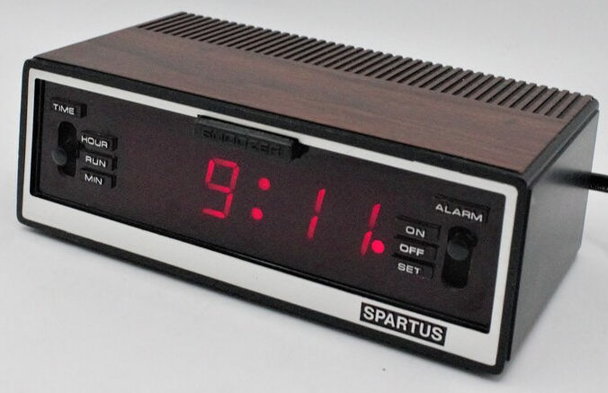
My great-grandparents got one of these watches back in the late 1970s. It was not quite the Spartus digital watch
shown above, but rather an East German clone of the same design (including the fake wood grain). This clock survived until,
unfortunately, my great-grandmother passed away about 10 years ago, and it disappeared when her estate was settled.
I used to hear stories about how that clock went everywhere with them: vacations, great-grandpa’s hospital stays, chemotherapy, until it found its permanent
residence in my grandmother’s living room after my great-grandpa passed away from cancer in the early 80s. For folks
who grew up in the true analog world, greeting the German Emperor as kids, making it through WW2, and then witnessing
the rise and fall of the Iron Curtain, this clock was truly a symbol of modernity and progress. For me, it was
great-grandpa—a symbol of a man who suddenly disappeared from my life when I was just a toddler.
If you ask kids today, it will be perceived as an unloved piece of junk at a yard sale.
In fact, East Germany bankrupted itself trying to keep up with the chip wars and
perception of modernity in the 70s and 80s. We were the Silicon Valley of the Eastern Bloc, but the fall of the Iron Curtain
and German reunification did not bail out the industry.
So, keeping up with the retro blog and the apparent appetite for classic embedded systems design, let’s look at some
real-world interfacing with MCS-51 series microcontrollers.
7-Segment Displays
Segmented displays have been around for over a century, with the first patents dating back to the early 1900s. With
Vacuum Fluorescent Display (VFD) technology becoming popular in the 1950s and 60s, 7-segment displays became a staple
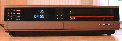
in digital clocks, calculators, and other electronic devices. The introduction of LEDs in the late 1960s further revolutionized
display technology, making 7-segment displays a staple from NASA spacecraft to VCRs (shown below).
Compared to discrete LED illumination, 7-segment displays offer a more compact and efficient way to display
numerical information without the loss of contrast seen in other display types. They are easy to read from a distance
or in challenging lighting conditions (e.g., outdoors, vending machines, household appliances, …).
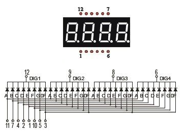
The displays typically consist of seven segments (labeled A to G) arranged in a figure-eight pattern, along with an optional decimal point (DP).
Each segment can be individually controlled to create various numerical digits (0-9) and some alphabetic characters, as
shown below. They typically come in two configurations: common anode and common cathode. In a common anode display, all the anodes of the segments are connected together,
while in a common cathode display, all the cathodes are connected together. This configuration affects how you control the segments
using the microcontroller. The segments typically come in blocks of 4, 8, or even 12 digits, and can be driven directly from the microcontroller.
Considering the challenges discussed in the previous post about conserving pins, we also need to consider how to drive multiple digits
with limited I/O pins. One common method is to use multiplexing, where each digit is activated one at a time in rapid succession.
This creates the illusion of all digits being lit simultaneously to the human eye, while only one digit is actually lit at any given moment.
This technique significantly reduces the number of I/O pins required to control multiple digits. In essence, you need to set the
segments and then select the right digit to display it on.
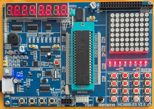
Staying with the HC680-ES2 development board from the previous post, we can connect an 8-digit 7-segment display to the microcontroller
using the following pin configuration:
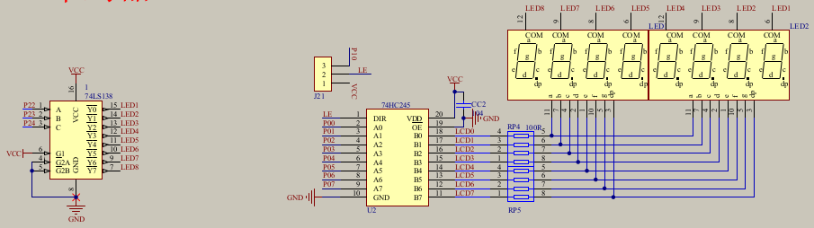
We use a 74HC138 3-to-8 line decoder to select which digit to activate, while the segments are connected to
a buffer 74HC245 to drive the segments. To avoid aliasing issues, the segments should be deactivated every time the
digit is switched. Since 8 bits are needed to encode the 7 segments plus the decimal point, we can use a single byte
to represent the segments to be lit. So the best way to do this for an MCU is to wire up an 8-bit GPIO port to the segments.
To map the segments efficiently to digits, we can use a lookup table (LUT) to map each digit (0-9) to its corresponding segment pattern.
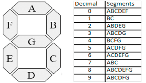
Since A-G and DP are mapped to bits 0-7 of the byte, we can create a LUT as follows:
#include <stdint.h>
const uint8_t segment_map[] = {
0b00111111,
0b00000110,
0b01011011,
0b01001111,
0b01100110,
0b01101101,
0b01111101,
0b00000111,
0b01111111,
0b01101111,
0b01110111,
0b01111100,
0b00111001,
0b01011110,
0b01111001,
0b01110001,
};
const uint8_t segment_dp = 0b10000000;
Now, just to test it, let’s start with a simple hex counter on the first digit. By default, the 3-to-8 decoder is already
mapped to LED8, so we can just interact with P0 to test the segments.
#define LED_DIGIT P0
void main(void) {
for(;;) {
for(uint8_t i=0; i<16; i++) {
LED_DIGIT = segment_map[i] | segment_dp;
for(uint16_t j=0; j<60000; j++);
LED_DIGIT = 0x00;
}
}
}
The end result looks as follows:
The full source can be found on GitHub.
Now, onto mapping multiple digits. We can simply shift the desired digit to P2.2-P2.4 to select the digit to display
on every iteration. To avoid flickering, we need to cycle through all digits rapidly. Here is a simple implementation
that displays a counting number on all 8 digits:
void delay(uint16_t t) {
while (t--)
;
}
void main(void) {
P0 = 0x00;
P2 = 0x00;
for(;;) {
for(uint8_t i=0; i<8; i++) {
P2 = i<<2;
LED_DIGIT = segment_map[i] | segment_dp;
delay(200);
LED_DIGIT = 0x00;
}
}
}
The end result looks as follows for the short delay (fast multiplexing):
If you slow it down enough, you can see the multiplexing effect:
The full source can be found on GitHub.
Odd Hardware Issues
Okay, there is an interesting problem with the 7-segment display on the HC6800-ES2 board. The segments mapped to P0.5 and P0.6 show correlated failures. Whenever P0.6 is low, it pulls P0.5 low as well. This is not a software issue,
as I have tested this with a simple loop that toggles these pins independently. Extensive component testing revealed
that the fault was solder residue. Given the $20 CAD price point of the board in 2020, I cannot complain too
much. After cleaning the board with
hexane (brake cleaner) and a brush, the issue disappeared. There was a 300 Ohm resistance between the two pins
when measured with a multimeter before cleaning. So, if you ever run into weird correlated pin issues on these boards,
try cleaning them first. The vendor of the dev kit should invest maybe another $1 CAD per board into ultrasonic
residue cleaning.
Conclusion
7-segment displays are a classic and effective way to display numerical information in embedded systems.
By using multiplexing techniques and lookup tables, we can efficiently control multiple digits with limited I/O pins.
Even though there is a serious retro vibe to these displays, they are still widely used in various applications where
contrast and readability are essential. In the next posts in the series, we will look at dot-matrix and character LCDs.
Further down the road, I want to wrap up the MCS-51 series with a custom design that revives the above clock.
Published: 2025-11-15
Updated : 2025-11-15
Not a spam bot? Want to leave comments or provide editorial guidance? Please click any
of the social links below and make an effort to connect. I promise I read all messages and
will respond at my choosing.