Sources available here
After going over the background of the 8051 architecture in part 1 of this series, let us have a look at a simple
“Hello World” example for this microcontroller. For this post, you either need an STC89C52 demo board, or you can
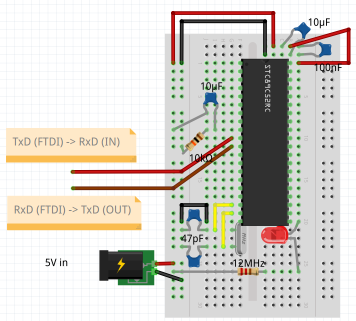
breadboard a minimal STC89C52-circuit as follows.
For the bootstrap on a breadboard you need:
- STC89C52RC microcontroller
- 12 MHz (or really anything between 1-25MHz) crystal oscillator
- Loading capacitors for the oscillator (go with 47pF or less for 12Mhz or more, and more for lower frequencies, preferably low ESR types)
- 10K pull-down resistor for reset
- 100nF, 10uF decoupling capacitors
- 10uF debouncing capacitor for the reset line (for stable power-up)
- An LED with a current-limiting resistor as an output indicator. Dimension the current limiting resistor, such that the sinking current does not exceed 6mA.
- An FTDI or other serial interface controller to use the bootstrap-loader of the STC to program the chip
This setup can be inferred from the sample schematic on page 12 of the datasheet.
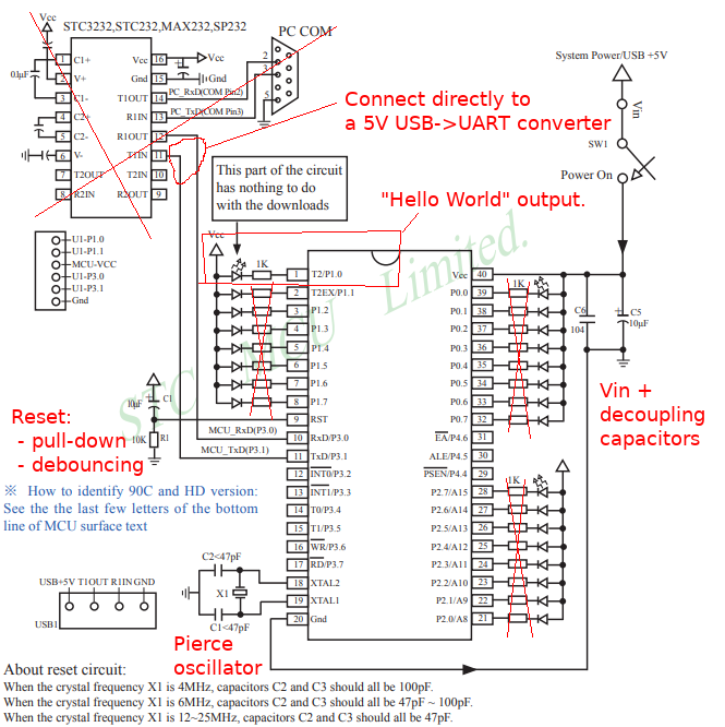
From the datasheet, it is very simple to derive the above bootstrap circuit. One eye-sore for users of any modern MCU is
probably the need for an external oscillator to boot. This was probably the drive inside STC to include additional internal
R/C oscillators in their more advanced STC12/15 variants. In addition to adding a mess of wires, the oscillator increases
BOM cost, and the number of component placements, and could become a failure source in high-impact applications. For
example, crystal oscillator failure recovery is a major concern for safety-critical applications that I had worked on
in my lab days. For example, impacts on the circuit could cause crystal fractures that cause the oscillator to fail
permanently or shift the frequency. The US Army has a good discussion about this. TL;DR, don’t build a cruise missile
or airbag controller just around a microcontroller fed by a single Pierce Oscillator. I digress, back to “Hello World” …
I’m using the HC6800-ES development
kit as a platform where D0 is already wired to P2_0. The complete sources are available here. The actual code for
blinking the LED looks like this.
#include <mcs51/8051.h>
static void delay(unsigned int t);
void main() {
for(;;) {
P2_0 = 0;
delay(30000);
P2_0 = 1;
delay(30000);
}
}
static void delay(unsigned int t) {
while (t--)
;
}
This can be compiled with SDCC. Please install SDCC and make sure it is in the PATH environment variable of your system.
If you save the above snippet to main.c, it can be compiled into an Intel hex for flashing as follows.
sdcc --Werror -mmcs51 --opt-code-size -o main.hex main.c
This can now be flashed with stcgal to the board as follows. Make sure stcgal
is also available in PATH.
stcgal.py -P stc89 -p /dev/ttyUSB1 main.hex
I had an issue where my STC89C52RC was from a new batch release that had a bootloader that was not supported by stcgal
yet. Luckily others already forked a version of stcgal that supports newer STC89s. I wish the original author would be
more responsive to pull requests, but sometimes it takes patience or own initiative. The command for nrifes fork of
stcgal to flash my STC89C52RC is as follows.
stcgal.py -P stc89a -p /dev/ttyUSB1 main.hex
After the above command is issued, connect power to your bread-board setup. Stcgal should handshake with the UART
bootloader and flash the image onto the chip. After flashing and power cycling you should see a red blinking LED as
follows.
That is how easy it is to program an 8051 chip with just open-source tools. The source also includes a sample of how to
use the meson build system to automate the compilation and flashing. Successful build automation is the first step
toward continuous integration. The next blog shows how to use an 8051 simulator to emulate parts of this chip. Because
this chip does not have in-system debugging support, any serious attempt to do continuous integration and testing likely
takes the form of software-based testing with a simulator. There might be a way to build a hardware-in-the-loop testing
system around this dev-kit, but this would be more tedious than what modern architectures like ARM, and RISCV provide via semihosting.
Published: 2022-06-04
Updated : 2025-10-04
Not a spam bot? Want to leave comments or provide editorial guidance? Please click any
of the social links below and make an effort to connect. I promise I read all messages and
will respond at my choosing.