In the previous posts, I gave a brief introduction to the 8051 series followed by a hands-on shallow dive to program a
widely available variant of the chip. Since none of the “simple” & low-cost alternatives offer decent direct debugging
support the best option to take a deeper dive at the architecture is a simulator. Before we get our hands dirty. Let us
revisit the Hello World code.
#include <mcs51/8051.h>
static void delay(unsigned int t);
void main() {
for(;;) {
P2_0 = 0;
delay(30000);
P2_0 = 1;
delay(30000);
}
}
static void delay(unsigned int t) {
while (t--)
;
}
… in machine form. Once you compile the example with sdcc, sdcc will generate an assembly listing of the code as hello.lst, here stripped down to the interesting pieces. Note this is not the disassembled binary flashed to the
board, but the intermediate representation of what is in hello.c.
...
      000000                        278 __interrupt_vect:
      000000 02r00r00         [24]  279     ljmp    __sdcc_gsinit_startup
      000000 02r00r03         [24]  294     ljmp    __sdcc_program_startup
      000003                        300 __sdcc_program_startup:
      000003 02r00r00         [24]  301     ljmp    _main
      000000                        314 _main:
                           000007   315     ar7 = 0x07
                           000006   316     ar6 = 0x06
                           000005   317     ar5 = 0x05
                           000004   318     ar4 = 0x04
                           000003   319     ar3 = 0x03
                           000002   320     ar2 = 0x02
                           000001   321     ar1 = 0x01
                           000000   322     ar0 = 0x00
      000000                        323 00102$:
      000000 C2 A0            [12]  325     clr _P2_0
      000002 90 75 30         [24]  327     mov dptr,#0x7530
      000005 12r00r12         [24]  328     lcall   _delay
      000008 D2 A0            [12]  330     setb    _P2_0
      00000A 90 75 30         [24]  332     mov dptr,#0x7530
      00000D 12r00r12         [24]  333     lcall   _delay
      000010 80 EE            [24]  334     sjmp    00102$
      000012                        344 _delay:
      000012 AE 82            [24]  345     mov r6,dpl
      000014 AF 83            [24]  346     mov r7,dph
      000016                        348 00101$:
      000016 8E 04            [24]  349     mov ar4,r6
      000018 8F 05            [24]  350     mov ar5,r7
      00001A 1E               [12]  351     dec r6
      00001B BE FF 01         [24]  352     cjne    r6,#0xFF,00110$
      00001E 1F               [12]  353     dec r7
      00001F                        354 00110$:
      00001F EC               [12]  355     mov a,r4
      000020 4D               [12]  356     orl a,r5
      000021 70 F3            [24]  357     jnz 00101$
      000023 22               [24]  358     ret
The listing shows how the C-code got translated into machine language. We see various jumps and calls to subroutines
and the program entry. There are also numerous data movement instructions to handle subroutine parameters, and local
variables, and to move data from constant locations. From the code, it becomes obvious that the MCS-51 has to have at
least 7 data registers (R0-R7), stack pointer (SP), a 16-bit data pointer (DPTR, broken out as DPL and DPH), an
accumulator (A), and some memory-mapped registers such as P2 for IO that appear to be bit-addressable via setb and clr.
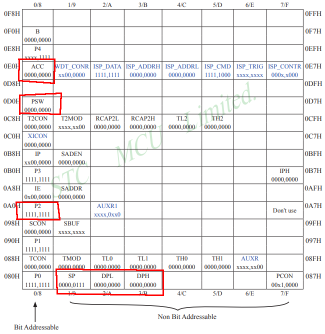
Dilling deeper it turns out that all registers except the program counter (PC) are memory-mapped in
what is called IRAM or data ram. STC shows this in their datasheet as follows.
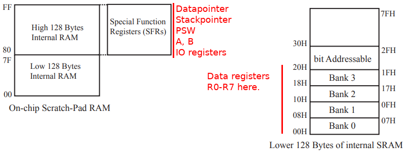
The rest of the available internal 256-byte RAM (IRAM) can be used as fast RAM for variables, and the stack. This is
hardly enough for complex operations, as such traditionally the original MCS-51 was able to access up to 64kB of
external memory that can be accessed via the IO pins. In more recent applications such as the STC89C52 there is also XRAM on board that can be accessed as a separate memory partition via movx instructions. In our example, we can fit
everything into IRAM.
The execution starts from the reset interrupt vector at location 0x0000. Note being a Harvard Architecture this is a
separate memory region from the memory segments shown before and in the case of the STC89C52xx, it is the first line
in flash memory. Most 8051 implementations service at least five interrupts from fixed memory locations, including
timers, external interrupts, and serial communications. In our case, we are just using the reset vector.
The first routine called is the stack and library initialization (__sdcc_gsinit_startup). The source can be found in mcs51/crtstart.asm of the SDCC compiler. In essence, this just sets the stack pointer into IRAM based on the
specifications in the linker file and initializes default memory regions. Then we jump to main (_main).
The bit of P2_0 is being cleared, and then we call the delay routine, using the DPTR register to pass the timeout
parameter for the delay. Since the 8051 is an 8-bit architecture it cannot operate on 16-bit registers directly. As
such the decrement is split up by the compiler into two stages of decrementing R6 and R7 in nested loops. As soon as
zero is reached we return back to main, set P2_0, and enter another delay loop.
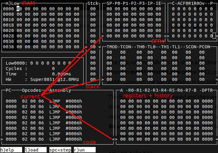
While there are quite a few options available, I really like Jari Komppa’s emu8051.
It is a very straightforward and simple code-base that could simulate a simple MCS-51 clone like the STC89C52 quite easily.
Moreover, the codebase is compact enough that it could be extended for custom peripherals, or easily split up into the
8051 core functions as a library, and the ncurses-based GUI code.
emu 00_hello.hex
Let’s look at this in emu8051. Once emu8051 is compiled per instructions it can be called directly on the hex file
generated by sdcc. By default, the simulator is halted at the reset vector. Pressing ‘r‘ starts the program, or one
can do a convenient instruction step with the space key. Pressing ‘v‘ toggles various views including the I/O view. By
default, the processor view is shown.
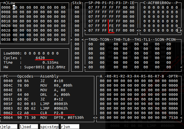
Running through the SDCC initialization takes about 6400 cycles (0.5ms). The change in port registers is shown below
after bit P_2.0 is cleared. Alternatively, the simulator also allows setting breakpoints.
While this nicely illustrates how the architecture works and demonstrates how crude debugging could be done, the real
beauty of emu8051 lies in its extensibility. The file emu.c contains the entire execution loop including GUI updates
that mostly consist of function calls to other files of the code-base. It is not that difficult to strip this down into
something that could be used for automated test cases. I created a fork of the simulator that provides a meson file to
separately build the executable and a library of core functions. The file testcase.c shows a simple test case that waits
for a certain number of cycles for the LED to be toggled. You could work this into test cases for your favorite
test-runner framework. You can build and test this for yourself by using meson instead of make to build the project.
meson build
ninja -C build
./build/testprog ../stc89c52-demos/build/00_hello.hex
Successfully toggled P2.0 after 534 instructions and 6408 cycles
This concludes a basic introduction to the STC89C52 series. In future posts, I want to dive further into peripheral
integration. Given the bare nature (i.e. not a lot of peripherals and memory), this is an excellent platform to revisit
some low-profile soft protocol implementations of various data buses. While this might seem archaic in modern times,
these needs arise when by accident the pinmux in an urgent production design was misplaced by the PCB designer, or a
lack of communication between the firmware and electrical teams caused some integration issues.
Published: 2022-07-03
Updated : 2025-10-04
Not a spam bot? Want to leave comments or provide editorial guidance? Please click any
of the social links below and make an effort to connect. I promise I read all messages and
will respond at my choosing.