All sources and design files can be found on GitHub.
After a busy week, I cleaned up my overflowing inbox over the weekend and found some real-time clocks, we got from one
of our reps that we hotlisted to evaluate for an upcoming project. Unfortunately, with brand-new parts, you do not
often get a development board or standard breakout boards. So I used an extended lunch break to fashion one in KiCAD 6.
Timekeeping in embedded systems can be tricky. For island solutions that are not connected to a network-time protocol
(NTP) source, GPS as a time source may be an option if the sky above the unit is open and there is enough power budget
to operate a GPS receiver. The cost of GPS modules has come down a lot over the years. However, for deeply embedded
systems, or solutions that would have to survive on a very low power budget a real-time clock may be needed. A lot of
these systems are often sensor systems that operate over brief periods and sleep most of the time. In many cases, this
can be as simple as reading one or more digital inputs, processing the data, and going back to sleep. If the RTC could
take over some event processing and only wake up the system to process such events in bulk, power consumption could be
greatly reduced. In other applications, wireless sensor networks rely heavily on time-domain-multiplexing for message
exchange. To keep the power consumption low the radio front-end is only switched on for a very brief amount of time on
a schedule to exchange data or route messages to the next hop in the network. Such systems also benefit from really
accurate low-power time-keeping.
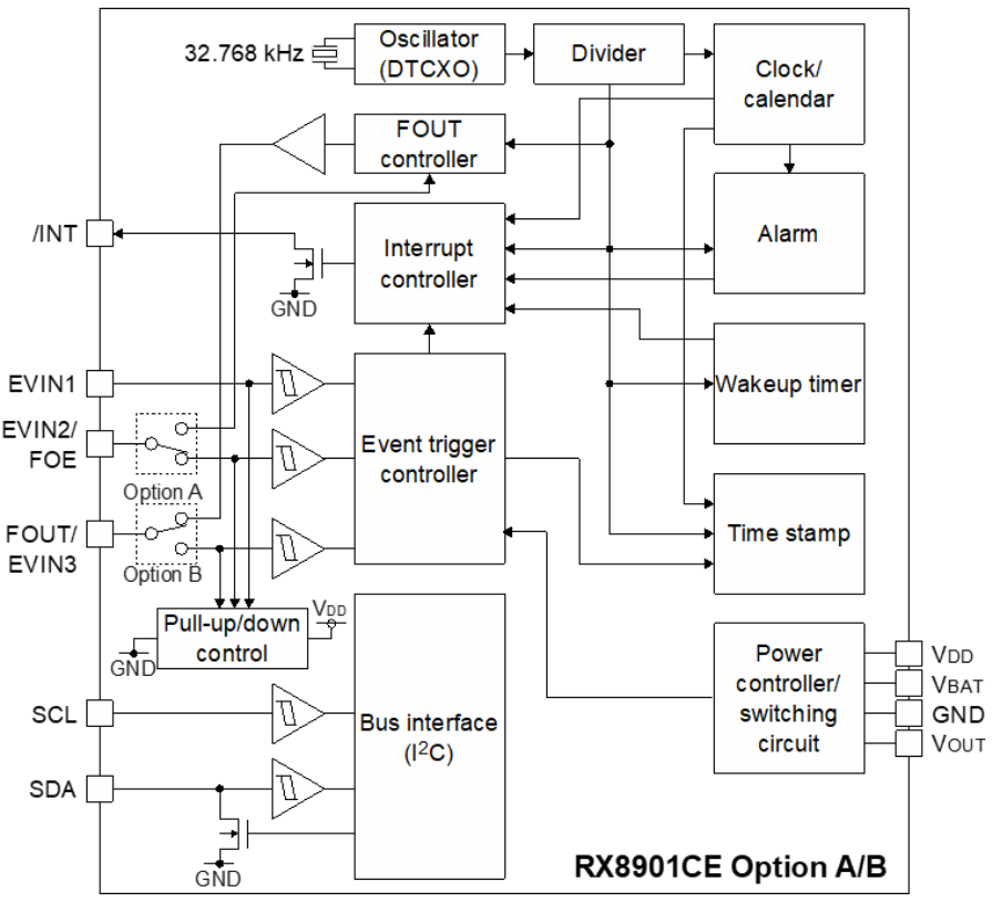
Well, one of our corporate reps recently introduced us to the Seiko Epson RX8901CE family of RTCs. Compared to
traditional RTCs this one packs quite a few features that make it fairly attractive to keep the BOM part count low. It
has a built-in crystal that on some variants can also be clocked out to other components near the module, it has
monitoring on up to three different event pins and comes in either SPI or I2C interface options, the package is
about the size of a standard small TXO, and has a built-in circuit for battery-failover (if the system power is lost).
It can actually monitor the battery voltage too and brown out if it gets too low. That is quite a powerhouse for
an RTC. Unfortunately, neither Seiko-Epson nor any known third parties provide a dev kit for it, making the evaluation
and prototyping a bit painful.
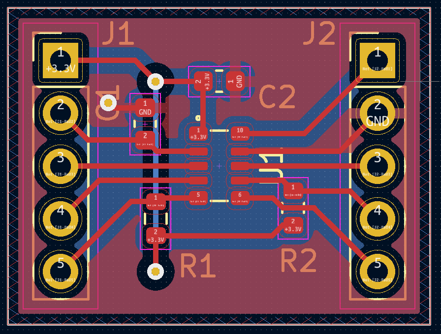
I used an extended lunch break on the weekend to turn the datasheet into a KiCad 6 library and fashion a minimal
break-out board for it, sources, and Gerber exports (for JLCPCB) can be found here.
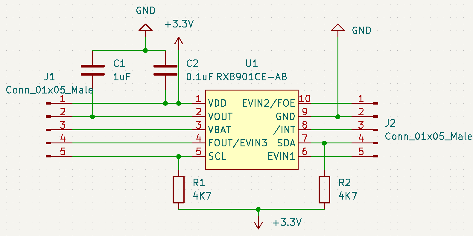
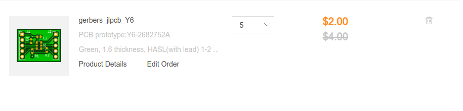
It turns out it is small enough, such that 5 boards could be had for $2 plus shipping. The internal regulator of the RTC
needs a 1uF bypass capacitor placed close to the chip as well, I added some optional 4K7 pull-ups to condition the I2C
interface and one bypass capacitor for VDD to account for switching noise across potentially longer jumper wires. With
snail mail, I am not in a hurry to test this anytime soon, this could be had for the amount I’d typically spend on a
Tim Hortons supply run. If you do not have the 0603 passives handy, you can also get them reasonably priced from LCSC.
There you have it, these days you can make your own five PCBs for $2 excluding shipping. With such competitive pricing,
I am hard-pressed to imagine, why anyone would want to invest $5K in home PCB-making equipment.
Once this board arrives, I will post another update on how to work with it and how to leverage some of these advanced
RTC features.
Published: 2022-10-29
Updated : 2025-10-04
Not a spam bot? Want to leave comments or provide editorial guidance? Please click any
of the social links below and make an effort to connect. I promise I read all messages and
will respond at my choosing.