All sources and design files can be found on GitHub.
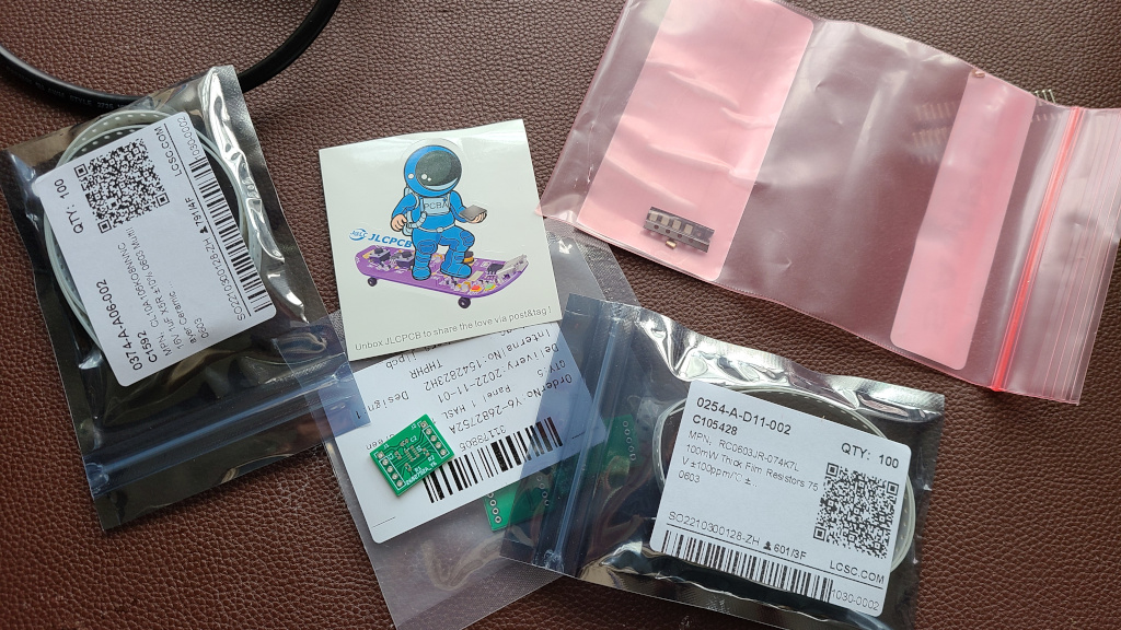
In part one of this series, I showed how to design a breakout board for the RTC8901CE chip. They just arrived in the
mailbag last week and I had a few minutes to piece them together and test them. Fast-forward I am really happy with the
quality and turn-around time of these PCBs. In the commercial world, 10 days turnaround from Asia usually incurs
significant shipping charges. This was not the case here. The mating parts that I did not have in my prototyping box
were the 4K7 0603 resistors and the 1uF 0603 regulator decoupling capacitor. I ordered them from LCSC, and they arrived
a day earlier.
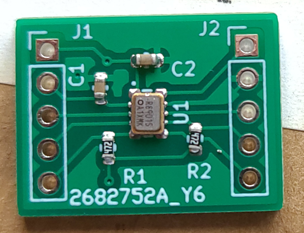
Fetching some long-expired solder paste and firing up the hot-air and the PCB was assembled in a few minutes. This is
how it looked after the first wash. Then hand-soldering some headers on. Then testing the power-up configuration, does
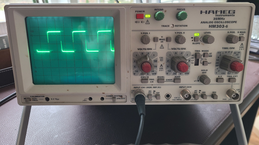
the chip work as 32.768KHz XO by default?
As you see my setup is a little dated, I had this Hameg oscilloscope since my high school days, way back in the 90s.
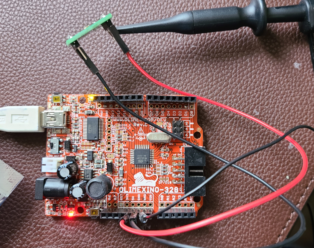
The really nice property of this Seiko-Epson chip is the very wide input voltage, you can work with this directly in
1.8V, 3.3V, or 5V logic domains without any level-shifters. I usually have an older Olimex Arduino clone in my handbag
that came in handy as a 3.3V or 5V power source.
Work is really intense these days, I am regularly putting in 13h hour-days. If I get an extended coffee break I will
test the other functions of this chip and publish them as an Arduino library in the same repository.
All sources and design files can be found on GitHub.
Published: 2022-11-12
Updated : 2025-10-04
Not a spam bot? Want to leave comments or provide editorial guidance? Please click any
of the social links below and make an effort to connect. I promise I read all messages and
will respond at my choosing.