Continuing the classic embedded systems series, let’s look at another common display technology: character LCDs.
In the late 1960s, segmented LCDs began to appear in control displays. The two major boosts were the development of the Twisted Nematic (TN) LCD in 1970, and the invention of the STN LCD in 1984, which allowed for better contrast.
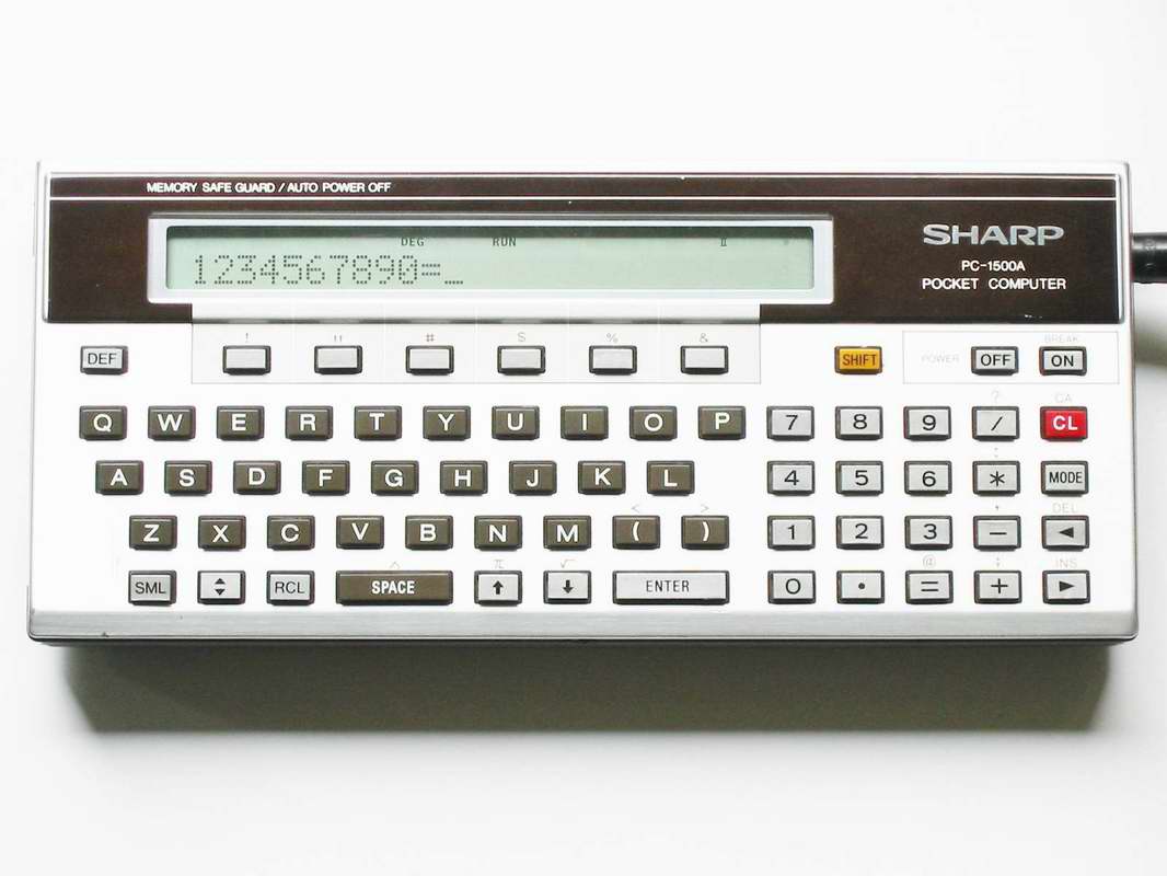
Throughout the 1980s and 1990s, character LCDs became a staple in consumer electronics, from calculators to early portable computers. Many Gen Xers will remember devices like the Sharp PC-1500A, or some Xillenials, whose parents couldn’t afford a C64 or Commodore Amiga, and ended up with a V-Tech PreComputer.

Transitioning from 7-segment displays to character LCDs was a significant step up in terms of usability and information density. In the good old days, people learned BASIC on 16x2 or 20x4 character LCDs, which allowed for displaying not only numbers but also text, making them ideal for user interfaces in embedded systems. Even in the 2010s, I designed the first generation of needle-free injectors for veterinary applications that used 16x2 character LCDs for user feedback and configuration.
HD44780 LCD Controller
Unlike the 7-segment display or LED matrix display, character LCDs typically use a dedicated controller chip to manage the display. Nearly all character LCDs you find today are based on the Hitachi HD44780 LCD controller standard, which was introduced in the early 1980s and now exists in numerous clones. The controller itself comes with a built-in character generator ROM that supports a standard set of characters, including alphanumeric characters and some special symbols. In the early days, there were three variants of the HD44780 controller:
- Japanese Standard Font
- European Standard Font
- Custom Font
These days, most LCDs come with a full ASCII and Japanese Katakana character set. All characters of the fonts are mapped
to 8x5 dot matrix patterns and are stored as such in the character generator ROM.
Now the HD44780 controller can operate in two modes: 8-bit mode and 4-bit mode. In 8-bit mode, all eight data lines (D0-D7)
are used for data transfer, allowing for faster communication. In 4-bit mode, only the upper four data lines (D4-D7) are used,
which reduces the number of required I/O pins on the microcontroller but requires two data transfers for each byte of data. This
was originally designed to support 4-bit microcontrollers, but is still widely used today to save I/O pins. I
uploaded the full datasheet for the HD44780 controller for reference. A further simplification is
to tie the R/W pin to ground, which makes the LCD write-only from the microcontroller’s perspective, as most operations
are purely timeout-based and do not require reading back from the LCD if the timing is respected with an acceptable margin.
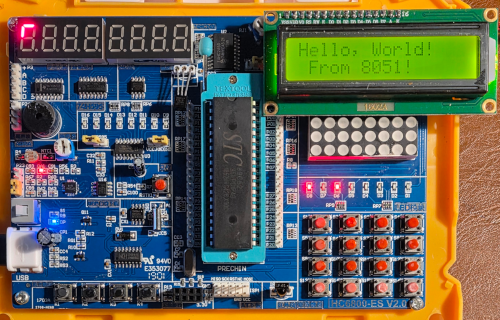
However, it turns out that despite only having an MCU with limited I/O pins, the HC6800-ES-V2.0 has the entire port P0 wired up to the LCD data lines D0-D7. So we can use the 8-bit mode for simplicity. RS, R/W, and E are connected to P2.6, P2.5, and P2.7, respectively. V0 is connected to a potentiometer for contrast adjustment.
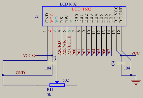
Which matches the datasheet reference circuit quite well.

Initializing the Display
What we inherited from the kit is a 16x2 character LCD, which means it can display 16 characters per line and has 2 lines,
and uses a 8x5 dot matrix for each character. To initialize the display, we need to send a series of commands to set it up
for operation. The initialization sequence at minimum involves the following steps:
- Wait for the display to come out of reset (usually a few milliseconds).
- Set the function set command to configure the display for 8-bit mode, 2-line display, and 5x8 dot character font.
Each command is latched by setting the RS pin high. On the falling edge, the command is read from the data bus by
the LCD controller.
- The
RS pin is set low for writes to the instruction register. It is set high for writes to the data register. - The
R/W pin is set low for write operations. It is set high for read operations.
With each command there is an expectation for maximum execution time. For most commands, this is around 37 microseconds, but for some commands like
clearing the display or returning the cursor to the home position, it can take up to 1.52 milliseconds. To keep things simple, we can use fixed delays after each command to
ensure the LCD has enough time to process them. Let’s start with the command and pin interface.
#define HD44780_E  P2_7
#define HD44780_RS P2_6
#define HD44780_RW P2_5
#define HD44780_DATA P0

#define HD44780_FUNC_SET        0x30
#define HD44780_DISP_CLEAR      0x01
#define HD44780_DISP_OFF        0x08
#define HD44780_DISP_ON         0x0C
#define HD44780_CURSOR_ON       0x0E
#define HD44780_CURSOR_OFF      0x0C
#define HD44780_CURSOR_BLINK    0x0F
#define HD44780_RETURN_HOME     0x02
#define HD44780_ENTRY_MODE      0x06
#define HD44780_2_ROWS          0x08
#define HD44780_POSITION        0x80
#define HD44780_ROW2_START      0x40
Now we need to create some helper functions to send commands to the LCD.
void delay(uint16_t t) {
while (t--)
;
}
void hd44780_byte(uint8_t d) {
HD44780_E = 1;
HD44780_DATA = d;
delay(10);
HD44780_E = 0;
delay(10);
}
void hd44780_command(uint8_t cmd) {
HD44780_RS = 0;
HD44780_RW = 0;
hd44780_byte(cmd);
delay(100);
}
Following Figure 23 from the HD44780 datasheet, we can implement the 8-bit initialization
sequence as follows:
void hd44780_init() {
delay(15000);
hd44780_command(HD44780_FUNC_SET);
delay(5000);
hd44780_command(HD44780_FUNC_SET);
delay(1000);
hd44780_command(HD44780_FUNC_SET);
delay(100);
hd44780_command(HD44780_FUNC_SET | HD44780_2_ROWS);
hd44780_command(HD44780_DISP_OFF);
hd44780_command(HD44780_DISP_CLEAR);
hd44780_command(HD44780_ENTRY_MODE);
}
With the row offset on the second row starting at address 0x40, we can now turn this into a simple hello world program.
void main(void) {
  hd44780_init();
  hd44780_command(HD44780_DISP_ON);
  hd44780_text("Hello, World!");
  hd44780_command((HD44780_POSITION | HD44780_ROW2_START) | 1);
  hd44780_text("From 8051!");
  for(;;) {
  }
}
The result looks as follows.
The full code can be found on GitHub.
Custom Characters
Looking closely at the character set, you will see that there are 8 repeating unused character slots in the beginning
column. The HD44780 controller allows us to define up to 8 custom characters by writing to the Character Generator RAM
(CGRAM).
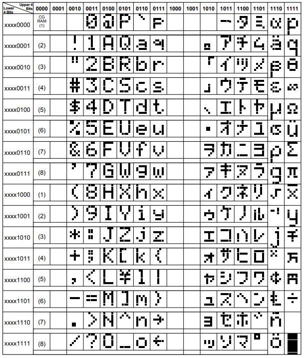
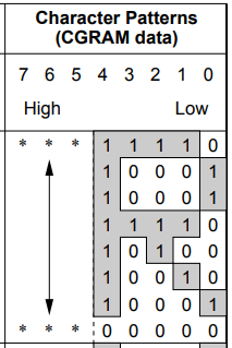
This is mapped to addresses 0x40 to 0x7F. Each row in the character generator rom is one row of the 5x8 dot matrix.
So you can simply bitmask 8 bytes per character to define your own patterns. There are even online generators that help you for arduino that can be pasted in
here. Let’s try a heart shape.
const uint8_t custom_char_heart[] = {
  0b00000,
  0b01010,
  0b11111,
  0b11111,
  0b11111,
  0b01110,
  0b00100,
  0b00000
};
Now we need to add the custom character to the CGRAM. We can do this by sending the appropriate command to set the CGRAM address,
#define HD44780_CGRAM_ADDR 0x40
#define HD44780_DRAM_ADDR 0x80
void hd44780_custom_char(uint8_t location, const uint8_t* charmap) {
location &= 0x7;
hd44780_command(HD44780_CGRAM_ADDR | (location << 3));
for (uint8_t i = 0; i < 8; i++) {
hd44780_data(charmap[i]);
}
hd44780_command(HD44780_DRAM_ADDR);
}
hd44780_custom_char(0, custom_char_heart);
Updating the main program to display the heart character:
void main(void) {
hd44780_init();
hd44780_custom_char(0, custom_char_heart);
hd44780_command(HD44780_DISP_ON);
hd44780_text("Hello, World!");
hd44780_command((HD44780_POSITION | HD44780_ROW2_START) | 1);
hd44780_data(0);
hd44780_text("From 8051!");
hd44780_data(0);
for(;;) {
}
}
The end result looks as follows.

Summary
Character LCDs based on the HD44780 controller are a staple in embedded systems, providing a simple and effective way
to display text and custom characters. The internal controller RAM is set up in a way that it takes in ASCII characters
directly. There is also the ability to define custom characters, which can be useful for creating simple graphics or symbols.
What I am missing on the dev kit is backlight control. This is hardwired on the dev kit. In a real-world application, you
would typically want to control the backlight. Either via a dedicated pin or using PWM for brightness control. This can
be a useful tool to save power or even from a UI perspective signal flashing error conditions.
As opposed to the 7-segment display, character LCDs are more versatile and can display a wider range of information.
However, they come at the cost of reduced contrast and viewing angles compared to LED-based displays. It is a good
compromise for many applications that operate indoors under constant lighting conditions. For outdoor or high-contrast applications,
you might want to consider OLED, e-ink displays instead, or classical 7-segment displays for numeric-only applications.
Published: 2025-11-17
Updated : 2025-11-17
Not a spam bot? Want to leave comments or provide editorial guidance? Please click any
of the social links below and make an effort to connect. I promise I read all messages and
will respond at my choosing.