As we continue our classic embedded systems series, let’s look at another common display technology that was used
frequently at the height of the MCS-51 era. As we saw in the previous article about LCDs,
by consolidating the controller for complex tasks into a single chip, we can greatly simplify the interfacing and
programming effort required to drive these displays. If you grew up as a Xillenial or Gen X, you may remember the first
Game Boy, which used a matrix monochrome LCD too; it even came with 4 colors per pixel.
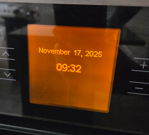
Looking at my 2007 Bosch stove (blog image above), these displays are still around today, although more modern displays
have taken over in recent years, as OLED and TFT displays have become more affordable and offer much better
contrast and colors.
Sitronix ST7920 LCD Controller
Full source here.
That said, the most dominant LCD controller for low-cost dot-matrix LCDs you will find is based on Sitronix’s ST7920 chipsets. This controller supports both graphic and text modes, making it versatile for various applications. It loosely
follows the design principles of the Hitachi HD44780 controller, which was widely used in character LCDs,
but Sitronix claims that it is a completely homegrown design (wink). Sitronix entered the market in the late 90s
and quickly dominated the low-cost LCD controller market by the 2010s.
The controller supports multiple interface modes, including 8-bit and 4-bit parallel interfaces, as well as a serial peripheral interface (SPI).
Unfortunately, the one I bought from Aliexpress has the configuration
pin PSB tied to GND, which forces it into serial mode only. The label reads 12864B-V2.3. Unfortunately, the online
references for older revisions of this display, which have PSB tied to a specific bridge resistor, don’t seem to be available
for this particular model; otherwise, I would have desoldered the bridge. This is a bit unfortunate, as the MCS-51 series
does not have SPI peripherals, and bit-banging SPI is not very efficient on this architecture.
For many platforms, you will find existing libraries that support the ST7920 controller, including u8glib, libdriver, and many others. Most of these libraries use the ST7920
in SPI mode, which makes perfect sense for more modern microcontrollers that have SPI peripherals built-in. One of the
issues, though, is that many of these are written in C++, and the ones that have C bindings are wrapped up in build
tools that are not very MCS-51 friendly (e.g., cmake, scons…). All the libraries shadow the display’s framebuffer to provide
advanced graphics capabilities, which is problematic for memory-constrained systems like the MCS-51 series. Worse, since the
MCS-51 needs special handling for RAM mapped to the XRAM space (either external RAM or additional internal RAM banks),
most libraries will not port easily.
For educational purposes, and to keep things minimalist, we will construct this driver from scratch with bit-banged SPI
in mind. Looking at the HC6800-ES-V2 schematic, we can see the following connections.
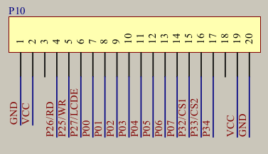
In SPI mode, we only need E (SCK P2.7), RS / RD (CS P2.6), and RW / WR (SID, P2.5), and if
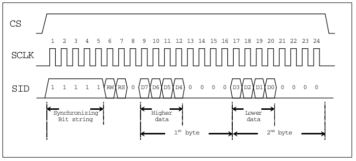
needed, RST (P3.4). Looking at the timing diagram, when PSB is low, we can clock in commands as follows.
This leads us to the following interface definitions. While the datasheet has elaborate initialization sequences for
8-bit and 4-bit parallel modes, the SPI mode is much simpler, as we can directly clock in commands and data. For
safety, the only command we need for a simple demo is the display ON command.
#define ST7920_SCLK P2_7
#define ST7920_CS P2_6
#define ST7920_SID P2_5
#define ST7920_RST P3_4

#define ST7920_DISP_ON         0x0C
As we see in the timing chart above, we can break up the transfer into 3 bytes (24 bits). In essence, we need to toggle SCLK and SID accordingly. SID is latched on the rising edge of SCLK. We can wrap this up in a simple loop for
8 bits.
void st7920_byte(uint8_t d) {
for(uint8_t i = 0; i < 8; i++) {
ST7920_SCLK = 0;
ST7920_SID = d & 0x80;
d <<= 1;
ST7920_SCLK = 1;
}
ST7920_SCLK = 0;
}
The distinction between command and data is done by setting the RS bit in the opening byte after the framing bits. Then
we break up the command and data byte into two nibbles as required by the ST7920 protocol.
void st7920_command(uint8_t cmd) {
ST7920_CS = 1;
st7920_byte(0b11111000);
st7920_byte(0xF0 & cmd);
st7920_byte(0xF0 & (cmd << 4));
ST7920_CS = 0;
}
void st7920_data(uint8_t data) {
ST7920_CS = 1;
st7920_byte(0b11111010);
st7920_byte(0xF0 & data);
st7920_byte(0xF0 & (data << 4));
ST7920_CS = 0;
}
Now what is left is the initialization and a convenience function to write directly into the character RAM. When the
ST7920 powers up, it starts in character mode by default and is set to auto-increment. So we can directly write data
to the first line of the display after initialization without going through elaborate setup sequences.
void st7920_text(const char* str) {
while (*str) {
st7920_data((uint8_t)(*str));
str++;
}
}
void st7920_init() {
ST7920_SCLK = 0;
ST7920_RST = 0;
ST7920_CS = 0;
delay(40000);
ST7920_RST = 1;
delay(40000);
}
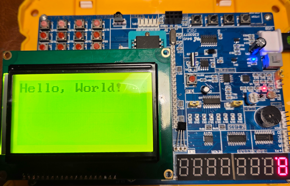
This leaves us with the following hello world program. No XRAM needed and ample space left in the IRAM for stack and variables.
void main(void) {
  st7920_init();
  st7920_command(ST7920_DISP_ON);

  st7920_text("Hello, World!");
  for(;;) {
  }
}
The end result looks as follows. Note the pin order is reversed on the 128x64 LCD compared to the HD44780 character LCDs,
I guess the HC600-ES2 board designer just copied the pinout from the existing header footprint without thinking too much about it.
It is a little crummy to fit the display, but it can be made to work.
Graphics Mode
Full source here.
Ok now that we have the text mode working, let’s see how we can leverage the graphic mode of the ST7920. The controller
itself has a 128x64 pixel graphic RAM, which is mapped in a somewhat peculiar way. The display is divided into two
halves of 128x32 pixels each. The second half is the overflow to the right of the first half. Each dot is represented
by one bit that is written in 16-bit increments. So to set a pixel at (x,y) we need to calculate the address accordingly. The
following function sets a pixel in graphic mode.
void st7920_pos(uint8_t x, uint8_t y) {
if(y >= 32) {
x += 8;
y -= 32;
}
st7920_command(ST7920_ADDR | (y & 0x3F));
st7920_command(ST7920_ADDR | (x & 0x0F));
}
Further, to get into graphic mode, we need to enable the extended instruction set and set the display to graphic mode. We
do this by using the extended function enable command.
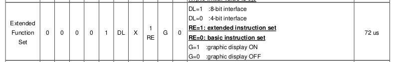
Setting the flag G determines whether the framebuffer is visible or not. So if we do not want to show aliasing effects
when erasing the framebuffer with clear_graphics(), we can initialize the display in extended mode, clear the framebuffer,
and then switch to graphics mode. The same can be done when buffering images in the background.
#define ST7920_EXTENDED_MODE 0x34
#define ST7920_GRAPHICS_MODE 0x36
void clear_graphics(void) {
for(uint8_t row = 0; row < 64; row++) {
st7920_pos(0,row);
for(uint8_t col = 0; col < 8; col++) {
st7920_data(0x00);
st7920_data(0x00);
}
}
}
void st7920_init() {
ST7920_SCLK = 0;
ST7920_RST = 0;
ST7920_CS = 0;
delay(40000);
ST7920_RST = 1;
delay(40000);
st7920_command(ST7920_EXTENDED_MODE);
clear_graphics();
st7920_command(ST7920_GRAPHICS_MODE);
}
So the first thing we can do is to draw a simple pattern on the display. For this, we can just iterate over all pixels
and set them based on a simple pattern. Here is a simple example that draws a running line pattern.
st7920_init();
for(;;) {
for(uint8_t row = 8; row < 64; row+=8) {
for(uint8_t col = 0; col < 8; col++) {
st7920_pos(col, row);
st7920_data(0xFF);
st7920_data(0xFF);
delay(50000);
st7920_pos(col, row);
st7920_data(0x0);
st7920_data(0x0);
}
}
}
Since we have a full graphic framebuffer, we can also draw bitmaps. For this, we need to prepare the bitmap data in a
suitable format. Each byte represents 8 vertical pixels, so we need to arrange our bitmap data accordingly. All that
can be done with simple tools and a bit of scripting. Staying with the inclusive theme of the early 1990s, lets use
a Cindy Crawford shoot by late Helmut Newton as our subject.

With a little bit of Gimp magic we can scale and dither the image to 128x64 pixels. Use Floyd-Steinberg dithering for best results, as
we only have 1-bit per pixel to work with.

With Python, we can now convert this into a C header file that we can include in our project.
The full source can be found here.
The things to keep in mind for the conversion. The 16-bit are written in MSB first order, so we need to reverse the bits in each byte. I might turn this into a tool later, but for now here is a simple
Python script that does the conversion. Also do not forget to invert the value since in the ST7920 a 1 bit
makes the pixel black.
With the generated header file we can now include the bitmap in our project and display it on the LCD.
#include "cindy.h"
void main(void) {
st7920_init();
for(uint8_t row = 0; row < 64; row++) {
st7920_pos(0, row);
for(uint8_t col = 0; col < 8; col++) {
st7920_data(cindy_crawford_helmut_newton_bitmask[row * 16 + col * 2]);
st7920_data(cindy_crawford_helmut_newton_bitmask[row * 16 + col * 2 + 1]);
}
}
for(;;) {
}
}
The end result looks as follows:

This is only scratching the surface of what can be done with the ST7920 controller. With some more effort, we could implement
line drawing algorithms, shapes, and even simple animations. One drawback to keep in mind for the ST7920 is that as soon
as you enable the extended instruction set, you lose access to the character RAM, so mixing text and graphics is not
straightforward. For simple status displays, this is not a big issue, but for more complex UIs, you may have to
save a font bitmap in graphic RAM and render text manually. This makes pre-existing libraries extremely flash and RAM
hungry.
Published: 2025-11-18
Updated : 2025-11-18
Not a spam bot? Want to leave comments or provide editorial guidance? Please click any
of the social links below and make an effort to connect. I promise I read all messages and
will respond at my choosing.