There are a few iconic, jellybean, or otherwise standard chipsets out there. Dating back to the days when on-die
peripherals were not common, Dallas Semiconductor (now Maxim Integrated, now part of Analog Devices) created a
number of popular devices that interfaced with microcontrollers using a single data line. The most famous of these
is probably the DS18B20 temperature sensor, but there are many others, including real-time clocks, memory chips,
and even iButton devices. Dallas Semiconductor was known for reliability and ease of use, making their devices
popular in embedded systems.
If you search popular model numbers on LCSC, you will see knockoffs and clones from at least 2-3 Chinese vendors.
Dallas 1-Wire Technology

I digress; back to Dallas Semiconductor. One major innovation was the 1-wire interface protocol.
Unlike traditional 8080 bus, SPI, or I2C interfaces, Dallas 1-Wire devices communicate over a single data line plus ground. This reduces wiring
complexity and cost, especially in applications where many devices are connected. The 1-Wire protocol uses time-based
signaling to differentiate between logical high and low states, allowing multiple devices to share the same bus.
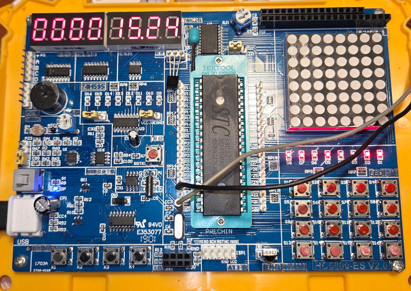
The datasheet for the temperature sensor DS18B20, which is
also included as part of the HC6800-ES2 kit, provides a good overview of the protocol. While the chip has actual Dallas markings, I have a feeling, given the accuracy, that it is probably a knockoff or clone. Nevertheless, the protocol should be the same.
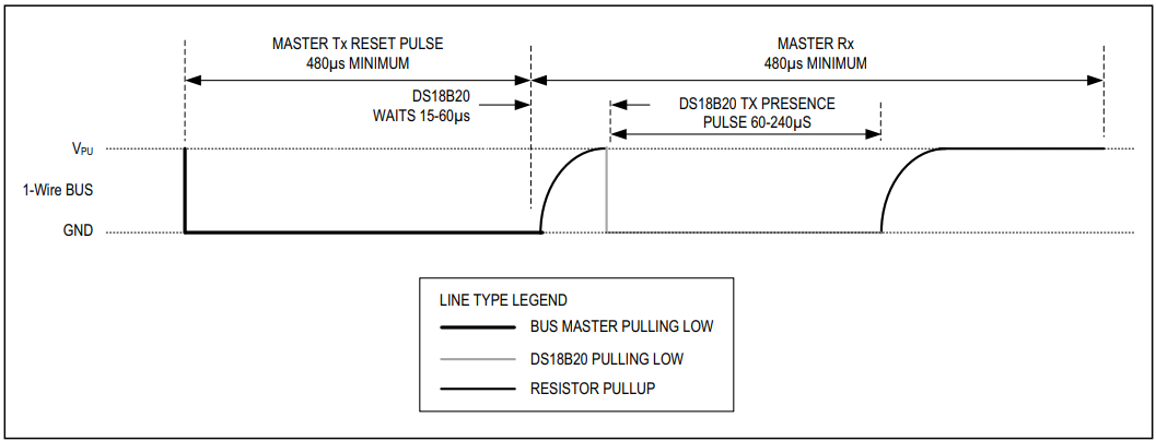
Communication begins with a reset pulse from the master (the microcontroller), followed by a presence pulse from the slave (the DS18B20).
To initiate communication, the master pulls the data line low for at least 480 microseconds. After releasing the line, the slave responds
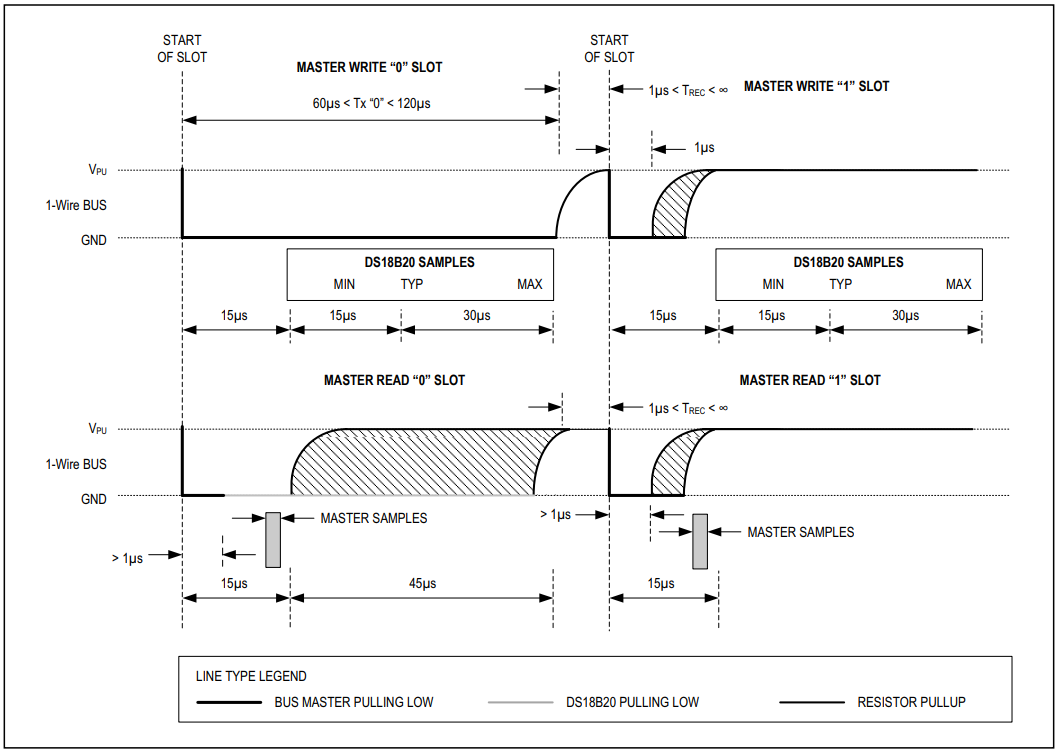
by pulling the line low for 60-240 microseconds, indicating its presence. Afterwards, the master can send commands to the
slave by writing bits to the bus. Each bit is transmitted within a time slot of 60 microseconds. To write a ‘1’, the master
pulls the line low for less than 15 microseconds and then releases it for the remainder of the time slot. To write a ‘0’, the master pulls
the line low for at least 60 microseconds.
There are various ways to implement this. One idea is to use a UART peripheral in a microcontroller to generate the timing.
However, the HC6800-ES2 wires the temperature sensor to a GPIO pin (P3.7). Therefore, we will bit-bang the protocol
using software delays. Given the crude timing of a 12 T MCS-51 core, using a timer and a state machine is probably not the best approach;
rather, we eyeball the timing with NOP instructions and loops to get reasonably close. Compiler optimization is not
your friend here, so be sure to indicate counters as volatile to prevent the compiler from optimizing them away.
A logic analyzer comes in handy to verify the timing.
So we arrive at the following minimal implementation. Note that some of these counters have been hand-tuned for a 12 T 12MHz
HC6800-ES2 system. Adjust as needed for other clock speeds or MCS-51 variants.
#define DS18B20_DQ P3_7
void delay(uint16_t t) {
while (t--)
;
}
void wire_init() {
DS18B20_DQ = 0;
delay(480);
DS18B20_DQ = 1;
delay(5);
while(DS18B20_DQ);
delay(500);
}
void wire_write_byte(uint8_t byte) {
volatile uint8_t j = 0;
for(uint8_t i = 0; i < 8; i++) {
DS18B20_DQ = 0;
j++;
DS18B20_DQ = (byte & 0x01);
j = 6;
while(j--);
DS18B20_DQ = 1;
byte >>= 1;
}
}
uint8_t wire_read_byte(void) {
volatile uint8_t j = 0, byte = 0;
for(uint8_t i = 0; i < 8; i++) {
DS18B20_DQ = 0;
j++;
DS18B20_DQ = 1;
j = 1;
while(j--);
byte |= (DS18B20_DQ<<i);
}
return byte;
}
That gives us all the building blocks we need to communicate with the DS18B20 temperature sensor. Next, we need to implement the higher-level commands
to read the temperature. The DS18B20 supports several commands, but for our purposes, we will focus on the Convert T and Read Scratchpad commands.
Also, as mentioned in the introduction, there could be multiple devices on the same 1-wire bus. Each device has a unique
64-bit ROM code that can be used to address it individually. However, if there is only one device wired up, most devices
support a Skip ROM command that allows the master to address all (or in this case, one device) devices on the bus simultaneously.
For the DS18B20, the skip ROM command is 0xCC, the start convert temperature command is 0x44, and the read scratchpad command is 0xBE.
Piecing this together, we arrive at the following code to read the temperature:
void ds18b20_start_conversion() {
wire_init();
wire_write_byte(0xCC);
wire_write_byte(0x44);
}
int16_t ds18b20_read_temperature() {
uint16_t temp = 0;
wire_init();
wire_write_byte(0xCC);
wire_write_byte(0xBE);
temp = wire_read_byte();
temp |= wire_read_byte() << 8;
return temp;
}
uint16_t temp_to_celsius(uint16_t raw) {
return (raw * 10) / 16;
}
Let’s Build Ourselves a Digital Thermometer
By piecing together the code snippets above, and what we learned from the 7 Segment Display article,
we can build a simple digital thermometer using the HC6800-ES2 kit and the DS18B20 temperature sensor.
Since we use delay loops to bit-bang the 1-wire protocol, our dynamic display update cannot live in the main loop. Instead, we
will use Timer 0 to periodically shift the digits on the 7-segment display, while the main loop handles reading the temperature and updating
the display buffer.
The full code can be found here.
So the end result looks like the blog image above.
Published: 2025-11-22
Updated : 2025-11-22
Not a spam bot? Want to leave comments or provide editorial guidance? Please click any
of the social links below and make an effort to connect. I promise I read all messages and
will respond at my choosing.